
Service Manual


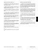


Table Of Contents
- Title Page
- Revision History
- Reader Comments
- Preface
- Table Of Contents
- 1 - Safety
- 2 - Product Records and Maintenance
- 3 - Kubota Diesel Engine
- 4 - Hydraulic System
- Specifications
- General Information
- Special Tools
- Hydraulic Schematics
- Hydraulic Flow Diagrams
- Troubleshooting
- Testing
- Traction Circuit Testing - Charge Pressure Test
- Traction Unit Testing - Wheel Motor Efficiency Tests
- Traction Circuit Testing - Piston Pump/Hydrostat Flow and Relief Pressure Test
- Cutting Unit Circuit Testing - Pressure Test
- Cutting Unit Circuit Testing - Reel Motor Efficiency/Case Drain Test
- Cutting Unit Circuit Testing - Reel Motor Cross-Over Relief Pressure Test (Reelmaster 3575-D)
- Cutting Unit Circuit Testing - Proportional Relief Valve (PRV) Pressure Test
- Cutting Unit Circuit Testing - Mow Control Manifold Relief Valve (RV) Pressure Test
- Cutting Unit Circuit Testing - Gear Pump (P1) Flow Test
- Steering/Lift Circuit Testing - Gear Pump (P2) Flow Test
- Steering/Lift Circuit Testing - Lift Relief Valve (RV1) Pressure Test (Reelmaster 3555-D and 3575-D)
- Steering/Lift Circuit Testing - Steering Relief Valve Pressure Test
- Steering/Lift Circuit Testing - Steering Control Valve and Steering Cylinder Test
- Adjustments
- Service and Repairs
- General Precautions for Removing and Installing Hydraulic System Components
- Check Hydraulic Lines and Hoses
- Priming Hydraulic Pumps
- Flush Hydraulic System
- Filtering Closed-Loop Traction Circuit
- Charge Hydraulic System
- Hydraulic Tank
- Radiator and Oil Cooler Assembly
- Hydraulic Pump Assembly
- Neutral Arm Assembly
- Piston Pump/Hydrostat
- Piston Pump/Hydrostat Service
- Gear Pump
- Gear Pump Service
- Front Wheel Motors
- Rear Wheel Motor
- Wheel Motor Service
- Cutting Unit Reel Motor
- Cutting Unit Reel Motor Service (Reelmaster 3550-D and 3555-D)
- Cutting Unit Reel Motor Service (Reelmaster 3575-D)
- Mow Control Manifold
- Mow Control Manifold Service
- Lift Control Manifold
- Lift Control Manifold Service (Reelmaster 3550-D)
- Lift Control Manifold Service (Reelmaster 3555-D and 3575-D)
- Control Manifold Cartridge Valve Service
- Steering Control Valve
- Steering Control Valve Service
- Steering Cylinder
- Steering Cylinder Service
- Front Lift Cylinders
- Rear Lift Cylinders
- Lift Cylinder Service
- 5 - Electrical System
- General Information
- Electrical Schematic
- Special Tools
- Troubleshooting
- Electrical System Quick Checks
- Adjustments
- Component Testing
- Ignition Switch
- Main Power Relay
- Fuses
- Fusible Links
- Toro Electronic Controller (TEC)
- Parking Brake Switch
- Neutral Switch
- Lower/Raise Joystick Switches
- Reel Enable/Disable Switch
- Mow/Transport Switch
- Seat Switch
- Backlap Switch
- Turn Around Switch (Reelmaster 3555-D and 3575-D)
- Engine Temperature Sender
- Start Relay
- Fuel Stop Solenoid
- Fuel Pump
- Glow Relay
- Hydraulic Solenoid Valve Coils
- Indicator Lights
- CAN-bus Termination Resistors
- Hour Meter
- Oil Pressure Switch
- Worklight Switch
- Service and Repairs
- 6 - Chassis
- 7 - DPA Cutting Units
- 8 - Belt Driven Groomer (Optional)
- 9 - Universal Groomer (Optional)
- 10 - Foldout Drawings
- Electrical Drawing Designations
- Reelmaster 3550-D Hydraulic Schematic
- Reelmaster 3555-D/3575-D Hydraulic Schematic
- Reelmaster 3550-D Electrical Schematic (machine serial numbers below 316000300)
- Reelmaster 3550-D (machine serial numbers above 316000300) Electrical Schematic
- Reelmaster 3555-D/3575-D Electrical Schematic
- Reelmaster 3550--D/3555--D/3575--D Electrical Schematic (Serial Numbers Above 403446001)
- Reelmaster 3550-D (machine serial numbers below 316000300) Wire Harness Drawing
- Reelmaster 3550-D (machine serial numbers below 316000300) Wire Harness Diagram
- Reelmaster 3550--D/3555--D/3575--D (Machine serial number 316000301 to 403446000) Wire Harness Drawing
- Reelmaster 3550-D (machine serial numbers above 316000300) Wire Harness Diagram
- Reelmaster 3550--D/3555--D/3575--D Wire Harness Drawing(Machine serial number 316000301 to 403446000)
- Reelmaster 3550--D/3555--D/3575--D Wire Harness Drawing Serial Numbers 403446001 to 405999999)
- Reelmaster 3550--D/3555--D/3575--D Wire Harness Drawing (Serial Numbers Above 406000000)

Reelmaster 3550−D/3555−D/3575−DHydraulic System Page 4 − 70
Filtering Closed−Loop Traction Circuit
Filtering of a closed−loop hydraulic system after a major
component failure (e.g. traction (piston) pump or wheel
motor) is a requirement to prevent debris from transmit-
ting throughout the system. If a closed−loop hydraulic
system filtering tool is not used (to ensure system clean-
liness) repeat failures and subsequent damage to other
hydraulic components in the system will occur. To effec-
tively remove contamination from closed−loop traction
circuit, use of the Toro high flow hydraulic filter and hy-
draulic hose kit are recommended (see Special Tools in
this chapter).
1. Park machine on a level surface, stop engine and re-
move key from ignition switch.
WARNING
Before jacking up the machine, review and follow
Jacking Instructions in Chapter 1 − Safety.
2. Raise and support machine so all wheels are off the
ground.
NOTE: If a wheel motor was replaced, install high flow
filter to the inlet (when traveling forward) of new wheel
motor instead of to the inlet (when traveling forward) of
the traction pump. This will prevent system contamina-
tion from entering and damaging the new motor.
3. Thoroughly clean junction of hydraulic hose and
lower fitting on rear wheel motor (Fig. 42). Disconnect
hose from lower fitting on wheel motor.
4. Connect Toro high flow hydraulic filter in series be-
tween wheel motor fitting and disconnected hose. Use
hydraulic hose kit (see Special Tools in this chapter) to
connect filter to machine. Make sure that fitting and hose
connections are properly tightened.
IMPORTANT: Use only hydraulic fluids specified in
Operator’s Manual. Other fluids could cause system
damage.
5. After installing high flow filter to machine, check and
fill hydraulic reservoir with new hydraulic oil as required.
6. Start engine. Run engine at low idle speed and check
for any hydraulic leakage from filter and hose connec-
tions. Correct any leaks before proceeding.
IMPORTANT: While engaging the traction circuit,
monitor the high flow hydraulic filter indicator. If the
indicator should show red, either reduce traction
pedal setting or reduce engine speed to decrease
hydraulic flow through the filter.
7. With engine running at low idle speed, slowly de-
press the forward traction pedal to the full forward posi-
tion to allow flow through the traction circuit and high
flow filter. Keep traction circuit engaged for five (5) min-
utes while gradually increasing both forward pressure
on traction pedal and engine speed. Monitor filter indica-
tor to make sure that green color is showing during op-
eration.
8. With engine running at high idle speed and traction
pedal moved to the forward direction, periodically apply
brakes to increase pressure in traction circuit. While
monitoring filter indicator, continue this process for an
additional five (5) minutes.
IMPORTANT: If using a filter that is not the bi−direc-
tional Toro high flow filter, do not press the traction
pedal in the reverse direction. If flow is reversed
when using a filter that is not bi−directional, debris
from the filter will re−enter the traction circuit.
9. With engine running at high idle speed, alternately
move traction pedal from forward to reverse. While mon-
itoring filter indicator, continue this process for an addi-
tional five (5) minutes.
10.Shut engine off and remove key from ignition switch.
11.Remove high flow hydraulic filter and hydraulic hose
kit from machine. Reconnect hydraulic hose to rear
wheel motor fitting. Make sure to properly tighten hose
(see Hydraulic Hose and Tube Installation in the Gener-
al Information section of this chapter).
12.Lower machine to ground.
13.Check oil level in hydraulic reservoir and add correct
oil if necessary.
Figure 42
1. Rear wheel motor 2. Lower fitting
FRONT
RIGHT
1
2