
Operator's Manual


g332520
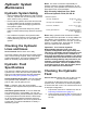
Figure85
MachineswiththeOptionalGrassShield
1.Locknut
3.Wheel-motorshaft
2.Hubandbrakedrum
4.Securethewheelhubtotheshaftwiththe
locknut(Figure84orFigure85),andtightenby
hand.
Note:Thebrakeshoesandbackingplatemust
concentricallyalignwiththebrakedrum.Ifthe
shoes,plate,anddrumaremisaligned,referto
theServiceManualforyourmachine.
5.Repeatsteps1through4attheothersideof
themachine.
InstallingtheWheel
1.Assemblethewheeltothehubwiththe4lug
nuts(Figure86),andtightenthelugnutsby
hand.
g332518
Figure86
1.Lugnut3.Hub
2.Wheel
2.Repeatstep1attheothersideofthemachine.
3.Removethejackstandsandlowerthemachine.
4.Torquewheellugnutsto95to122∙Nm(70to90
ft-lb)inacrossingpattern.
5.Torquethelocknutisto339to372N∙m(250to
275ft-lb).
6.Checkparkingbrakeandadjustitifnecessary;
refertoCheckingtheParkingBrake(page28).
56