
Service Manual


Hydraulic
System
Reelmaster 6500-D/6700-D Hydraulic SystemPage 4 - 81
Rear (6700 -D #6 or 7 Only)
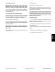
A. Remove both lock nuts and upper link plate. Re-
move upper link and rollers from the lift arm and cylin-
der clevis (Fig. 52).
B. Remove retaining ring from the cylinder cap end
pin. Remove cylinder pin with r emaining retaining
ring from the frame and cylinder clevis (Fig. 52).
C. Install in reverse order. Use a drop of medium
strength thread locking compound to secure the lock
nuts.
1. Lock Nut
2. Upper Link Plate
3. Upper Link
4. Roller
5. Retaining Ring
6. Cylinder Cap End Pin
7. Lift Arm
8. Lower Link Plate
Figure 52
4
6
5
1
2
3
8
7
8