
Service Manual


Units
DPA Cutting
Rev. EReelmaster 6500--D/6700--D
DPA Cutting Units
Page 7.2 -- 37
Disassembly (Fig. 39)
1. Position machine on a clean and level surface, lower
cutting units, stop engine, engage parking brake and re-
move key from the ignition switch.
2. To remove roller brush from brush shaft:
A. Remove the non--drive brush bearing housing
(item 30) from cutting unit.
B. Slide excluder seal from roller brush shaft.
C. Remove lock nut and J--bolt from both ends of the
brush.
D. While rotating brush, slide brush from the shaft.
3. Disassemble roller brush components as necessary
using Figures 39 as a guide.
Assembly (Fig. 39)
1. If brush was removed from shaft, slide brush onto
shaft while rotating brush. Secure brush to shaft with two
(2) J--bolts and lock nuts. Make sure that the J--bolts are
installed with the threaded portion on the outside of the
brush (Fig. 40). Torque lock nuts from 20 to 25 in--lb (2.3
to 2.8 N--m).
2. If seals or bearings were removed from brush bear-
ing housings, install new components noting proper ori-
entation as shown in Figure 41.
A. Pack bearings with grease before installation.
B. Press bearing into bearing housing so that bear-
ing contacts shoulder in housing bore.
C. Install grease seals so that seal lips are posi-
tioned toward the brush location. Press inner seals
into housing so that seal contacts bore shoulder.
Press outer seals into housing until inner seal is con-
tacted.
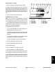
1. Roller brush shaft
2. J--bolt
3. Roller brush
4. Lock nut
Figure 40
1
2
3
4
20 to 25 in--lb
(2.3 to 2.8 N--m)
1. Bearing
2. Inner grease seal
3. Outer grease seal
4. Housing (non--driven)
5. Housing (driven)
Figure 41
2
2
1
1
4
5
3
3