
Operator's Manual


14
Setup
Note: Determine the left and right sides of the machine from the normal operating position.
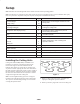
Note: Use this chart as a checklist to ensure that all parts necessary for assembly have been received. Without these parts,
total set-up cannot be completed. Some parts may have already been assembled at the factory.
Description Qty. Use
Counterweight
Large o-ring
5
10
Mounting the counterweights and motors to the
cutting units.
Lynch pin
Steering locking pin
5
5
Mounting the cutting units to the traction unit
Locking the cutting units
Diagnostic ACE display overlay 1
Diagnosing machine malfunctions (store in
service shop until needed)
Key 1 Use with hood lock
Key ring 1 Contains keys
Gauge bar
Screw
Wing nut
1
2
2
Setting cutting units, refer to Cutting Unit
Operator’s manual
EEC decals 4 Apply to machine for CE
EEC certificate 2
Operator’s manual (traction unit) 2 Read before operating the machine.
Parts catalog 1
Registration card 1 Fill out and return to Toro.
Installing the Cutting Units
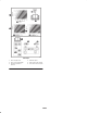
Cutting unit models 03860, 03861, and 03862 can be
installed at any of the five mounting locations on the
traction unit. Figure 2 shows the orientation of the
hydraulic drive motor for each of the five locations. For
any of the locations requiring the motor to be mounted on
the right end of the cutting unit, install a counter weight on
the left end of the cutting unit. For the locations requiring
the motor to be mounted on the left end, install a counter
weight on the right end of the cutting unit.
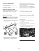
Note: Counterweight mounting capscrews are shipped
installed on the right bearing housing of the cutting units.
The capscrews on left bearing housing are to be used for
securing the hydraulic motor.
Motor Weight
Motor Weight Weight Motor
Weight Motor Weight Motor
#1#4 #5
#3
#2
Figure 2
1. Remove cutting units from cartons. Assemble and
adjust per Cutting Unit Operator’s Manual.
2. Remove protective plugs from each end of cutting unit.