
Operator's Manual
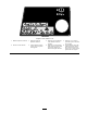


Figure 9
1. Traction pedal 6. Parking brake latch
2. Forward speed limiter 7. Locking pin
3. Red diagnostic light 8. Reverse speed limiter
4. Speedometer 9. Key switch
5. Brake pedals
Forward Speed Limiter
Preset the forw ard speed limiter ( Figure 9 ) to limit
the amount the traction pedal can be de pressed
in the forw ard direction to maintain a constant
mo wing speed.
Red Diagnostic Light
T he red diagnostic light ( Figure 9 ), located on
steering to w er , is used to con v ey sev eral different
messag es . W hile star ting the mac hine , the light
will illuminate when the glo w plugs are on.
If the light blinks during operation, it ma y indicate
any of the follo wing:
• T he mac hine is being operated faster than the
maxim um speed v alue initially prog rammed
into the ECU .
• An electrical malfunction has been detected
(open or shor ted output.
• A h y draulic leak has been detected (Only if
T urfdefender leak detector is installed on
mac hine)
• A comm unications er ror has been detected
(Only if T urfdefender leak detector is installed
on mac hine)
Key Switch
T he k ey switc h ( Figure 9 ) has three positions:
OFF , ON/Preheat and ST AR T .
Speedometer
T he speedometer ( Figure 9 ) indicates g round
speed at whic h mac hine is tra v eling .
Brake Pedals
T w o brak e pedals ( Figure 9 ) operate indi vidual
wheel brak es for tur ning assistance , parking,
and to aid in obtaining better sidehill traction.
Loc king pin connects the pedals for parking brak e
operation and transpor t.
Parking Brake Latch
A knob on the left side of console actuates parking
brak e loc k ( Figure 9 ). T o eng ag e parking brak e ,
connect pedals with loc king pin, push do wn on
both pedals and pull parking brak e latc h out. T o
release parking brak e , de press both pedals until
parking brak e latc h retracts .
Reverse Speed Limiter
Adjust the screw ( Figure 9 ) to limit the amount the
traction pedal can be de pressed in the rearw ard
direction to limit speed.
Lower Mow/Raise Control Lever
(Joystick)
T he lev er ( Figure 10 and Figure 11 ) raises and
lo w ers the cutting units and also star ts and stops
the reels .
18