
Operator's Manual


7. Inser t the horizontal shaft of the pi v ot kn uc kle
into the mounting tube of the car rier frame
( Figure 5 ).
8. Secure pi v ot kn uc kle to car rier frame with a
thr ust w asher , flat w asher and a flang e head
capscrew ( Figure 5 ).
9. Inser t a thr ust w asher onto v er tical shaft of
pi v ot kn uc kle ( Figure 5 ).
10. If remo v ed, inser t the v er tical shaft of the
pi v ot kn uc kle into lift ar m pi v ot hub ( Figure 5 ).
Guide the pi v ot kn uc kle in place betw een the
tw o r ubber centering bumpers in the under
side of the lift ar m steering plate .
11. Inser t the lync h pin into the cross hole on the
pi v ot kn uc kle shaft ( Figure 5 ).
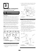
12. R emo v e n ut securing turf compensation spring
mounting brac k et to cutting unit stabilizer ear
( Figure 6 ). Inser t tipper c hain onto capscrew
and secure with n ut remo v ed.
Figure 6
1. Lift chain 2. Cutting unit stabilizer ear
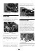
13. Mount the motor to the dri v e end of the
cutting unit and secure with tw o capscrews
pro vided ( Figure 7 ).
Figure 7
1. Motor
2. O-ring
Note: If fix ed cutting unit position is
required, inser t steering loc king pin into pi v ot
kn uc kle mounting hole ( Figure 5 ).
14. Hook spring wire around bottom of steering
loc king pin ( Figure 5 ).
Step
3
Making Alternate Cutting
Unit Adjustments
No Parts Required
Procedure
T he factor y sets the tractor appropriately for
most fairw a y mo wing applications . Sev eral
adjustments for fine-tuning the mac hine
for par ticular applications are included in
Cutting Unit Maintenance , pag e 48 , as follo ws:
• Adjusting the turf compensation spring
Adjusts the amount of fore and aft rotation
a v ailable , the amount of g round clearance in
transpor t, and transfers the w eight from the
front to rear roller , reducing bobbing (a w a v e
patter n in the turf).
• Adjusting the cutting unit lo w ering rate
Adjusts the speed at whic h the cutting units
lo w er .
15