
Service Manual


Reelmaster 6500–D/6700–D
Page 6 – 10
Axles, Planetaries and Brakes
Brake Service
1
2
5
6
9
4
8
7
10
75 – 85 ft–lb
75 – 85 ft–lb
75 – 85 ft–lb
3
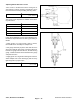
Figure 14
1. Capscrew 5. Flange head capscrew 9. Planetary wheel drive
2. Wheel motor 6. Brake assembly 10. Flange head capscrew
3. O–ring 7. Splined shaft
4. Brake cable 8. Retaining ring
Remove Brake Assembly (Fig. 14)
1. Drain oil from planetary wheel drive (9) and brake as-
sembly (6).
2. Jack up front of machine and support with jack
stands.
3. Remove wheel.
4. Remove wheel motor (2) (see Removing Hydraulic
System Components in Repairs section of Chapter 4
– Hydraulic System).
5. Disconnect brake cable (4) from pull rod on brake.
6. Remove flange head capscrews (5) securing brake
assembly to frame; be careful not to drop splined shaft
as brake assembly is removed.
7. Remove splined shaft (7).
8. Do brake inspection and repair as shown on next
page.
Install Brake Assembly (Fig. 14)
1. Install splined shaft (7) into brake assembly.
2. Install brake assembly onto frame, aligning splined
shaft with input shaft on planetary wheel drive.
3. Install flange head screws (5) to secure brake assem-
bly to frame. Tighten screws in a crossing pattern to a
torque of 75 – 85 ft–lb.
4. Install brake cable (4)to pull rod on brake assembly.
5. Install new o–ring (3) on wheel motor (2). Install wheel
motor and tighten capscrews (1) to a torque of 75 – 85
ft–lb.
6. Make sure drain plug is installed in bottom of brake
assembly. Fill planetary wheel drive with SAE 85W–140
gear lube. Capacity is approximately 16 oz. per wheel
(both planetary drive and brake housing).