
Service Manual


Reelmaster 6500–D/6700–D
Page 4 – 93
Hydraulic System
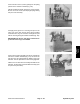
34. Put the three 1/2 in. (13 mm) springs into the spring
pockets of the isolation manifold (Fig. 115).
NOTE: Two different length springs are used in the unit.
Be sure to use the 1/2 in. (13 mm) length springs during
this part of the assembly.
35. Apply clean grease to a seal ring and put it in the
valve ring recess that will face down when installed.
Install the valve ring over the bolts and alignment pins
with the seal ring facing the isolation manifold (Fig. 116).
IMPORTANT: Be sure the seal ring is seated correct-
ly after the valve ring is assembled.
36. Put the hex drive assembly, pin side up, through the
hole in the isolation manifold (Fig. 117). the slot in the
hex drive must be engaged with the SMALL tang of the
drive link. Turn the input shaft to assist the engagement.
NOTE: If the hex drive does not readily assemble on the
drive link, the drive link was assembled incorrectly (See
step 22 of this procedure).
Figure 115
Figure 116
Figure 117
Hydraulic
System