
Operator's Manual


2. Close the by-pass valve before starting the engine.
However, do not exceed 7–11 Nm torque to close the
valve.
IMPORTANT: Running the engine with the by-pass valve
open will cause the transmission to overheat.
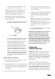
DIAGNOSTIC LIGHT (Fig. 19)
The RM 6500-D is equipped with a diagnostic light which
indicates whether or not the electronic controller is function-
ing correctly. The diagnostic light is located on the steering
tower panel. When the electronic controller is functioning cor-
rectly and the key switch is moved to the ON position, the
controller diagnostic light will be illuminated for approxi-
mately 6 seconds. The light will not illuminate if the con-
troller detects a malfunction in the electrical system.
If the diagnostic light is not illuminated when the key switch
is in the ON position, this indicates that the electronic con-
troller is not operating. Possible causes are:
1. Loopback connector (under control panel cover) is not
connected.
2. The electronic controller light is burned out.
3. Fuses are blown.
4. The light is not functioning correctly.
Check electrical connections, input fuses and the diagnostic
light bulb to determine malfunction. Make sure the loopback
connector is secured to the wire harness connector.
DIAGNOSTIC ACE DISPLAY
The RM 6500-D is equipped with an electronic controller
which controls most machine functions. The controller deter-
mines what function is required for various input switches
(i.e. seat switch, key switch, etc.) and turns on the outputs to
actuate solenoids or relays for the requested machine function.
For the electronic controller to control the machine as desired,
each of the input switches, output solenoids and relays must
be connected and functioning properly.
The Diagnostic ACE display is a tool to help the user verify
correct electrical functions of the machine.
22
Figure 19
1. Electronic controller light
➀