
Operator's Manual


24
ed. If the “inputs displayed’ LED is illuminated,
press the toggle button on Diagnostic ACE to
change LED to “outputs displayed”.
Note: It may be necessary to toggle between
“inputs displayed” and “outputs displayed” sev-
eral times to do the following step. To toggle
back and forth, press the toggle button once.
This may be done as often as required. DO
NOT HOLD THE BUTTON.
6. Sit on the seat and attempt to operate the
desired function of the machine. The appropri-
ate output lights should illuminate to indicate
that the ECU is turning on that function. (Refer
to the list below to be certain of the specified
output lights.
Note: If any output light is blinking, this indicates an
electrical problem with that OUTPUT. Repair or
replace defective electrical parts immediately. To
reset a blinking light, turn the key switch to “OFF”,
then back to “ON”.
If no output lights are blinking, but the correct out-
put lights do not illuminate, verify that the required
input switches are in the correct positions for the
function to occur.
If the output lights are on as specified, but the
machine does not function properly, this indicates a
non-electrical problem. Repair as necessary.
Note: Due to electrical system constraints, the output
lights for “START”, “PREHEAT” and “TR/ALT”
may not blink even though an electrical problem
may exist for those functions. If the machine prob-
lem appears to be with one of these functions, check
the electrical circuit with a volt/ohm meter to verify
that no electrical problem exists to these functions.
If each input switch is in the correct position and
functioning correctly, but the output lights are not
correctly illuminated, contact your Toro Distributor
for assistance.
IMPORTANT: The Diagnostic ACE display must
not be left connected to the machine. It is not
designed to withstand the environment of the
machine's everyday use. When finished using the
hold the button down.
6. The Diagnostic ACE will illuminate the light
associated with each of the inputs when that
input switch is closed.
Individually, change each of the switches from
open to closed (i.e., sit on seat, engage the trac-
tion pedal, etc.), and note that the appropriate
light on Diagnostic ACE will blink on and off
when corresponding switch is closed. Repeat on
each switch that is possible to be changed by
hand.
7. If switch is closed and appropriate light does not
turn on, check all wiring and connections to the
switch and/or check switches with an ohm meter.
Replace any defective switches and repair any
defective wiring.
The Diagnostic ACE also has the ability to detect
which output solenoids or relays are turned on. This is
a quick way to determine if a machine malfunction is
electrical or hydraulic.
To verify output function:
1. Park the machine on a level surface, lower the
cutting units, stop the engine and engage the
parking brake.
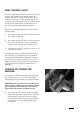
2. Open the control panel cover. Locate the wire
harness and connectors near the controller.
Carefully unplug the loopback connector from
the harness connector. Set the height-of-cut selec-
tor knob to position “A”.
3. Connect the Diagnostic ACE connector to the
harness connector. Make sure the correct overlay
decal is positioned on Diagnostic ACE.
4. Turn the key switch to the ON position, but do
not start the machine.
Note: The red text on the overlay decal refers to
input switches and the green text refers to out-
puts.
5. The “outputs displayed” light, on lower right col-
umn of the Diagnostic ACE, should be illuminat-