
Service Manual


20
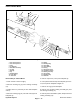
Front Traction Motor
1
2
3
12
11
6
7
21
22
19
18
17
8
16
13
14
15
14
13
4
5
10
Figure 61
1. Hex Head Cap Screw
12. Washer
2. Hex Head Cap Screw
13.
Retaining Ring
3. Plug
14.
Thrust Ring
4. O–Ring Seal
15.
Thrust Bearing
5. Back Plate Assembly
16. Bearing
6. O–Ring
17.
Housing Assembly
7. Bearing
18. Camplate Assembly
8. Key
19.
Rotating Assembly
9. Retaining Ring
20.
Grass Shield
10. Drive Shaft
21.
Retaining Ring
11. Shaft Seal
22. Shaft Seal
Disassembly of Traction Motor
5. Remove capscrews (1 & 2) from backplate (5).
1. Clean outside of unit thoroughly.
6. Use a plastic mallet and tap the backplate (5) to loos-
en it; then pull the backplate straight out.
2. Remove retaining ring (9) from housing assembly
(17).
7. Remove O–ring (6) from backplate.
3. Clamp shaft in a protected jaw vise with backplate
8. Remove the complete rotating assembly (19) from
end up.
the housing assembly (17).
4. Remove retaining ring (21) and shaft seal (22) from
9. Remove piston assemblies, spider, and pivot from the
backplate (5).
rotating assembly (19).
Hydraulic System
Page 4 – 72
Reelmaster 4500–D
9