
Service Manual


Reelmaster 5010 Series Page 5 -- 19 Electrical System
Check Operation of Interlock Switches
CAUTION
The interlock switches are for the protection of
the operator and bystanders and to ensure cor-
rect operation of the machine. Do not bypass or
disconnect switches. Check the operation of the
interlockswitchesdailyforproperoperation.Re-
place any malfunctioning switches before oper-
ating the machine.
Interlock switch operation is described in the Traction
Unit Operator’s Manual. Your Reelmaster is equipped
with an Electronic Control Module (ECM) which moni-
tors interlock switch operation. Information on the ECM
is described in the Traction Unit Operator’s Manual and
in the Component Testing section of this Chapter.
The interlock system used on your Reelmaster includes
the seat switch, the traction neutral switch, the parking
brake switch, the cutting unit up limit switch, the mow/
transport switch, the PTO switch and two (2) cutting unit
backlap switches. Testing of individual interlock
switches is included in the Component Testing section
of this Chapter.
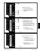
NOTE: Use the Diagnostic Display (see Special Tools
in this chapter) to test Electronic Control Module inputs
and outputs before further troubleshooting of an electri-
cal problem on your Reelmaster.
Electrical
System