
Operator's Manual


g375690
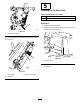
Figure18
1.Carriagebolt(3/8x1-1/4
inches)
3.Flangelocknut(3/8inch)
2.Turf-compensatorbracket
3.Removetheangelocknut(3/8inch)thatsecures
thecapscrewoftheturfcompensationspringto
therighttabofthecarrierframe,andremovethe
compensationspringfromthecuttingunit(Figure19).
Note:Donotremovetheangeserratednutfrom
thecapscrew.
g375691
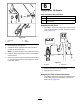
Figure19
1.Capscrew3.Flangelocknut(3/8inch)
2.Righttab(Carrierframe)
4.Assemblethecapscrewoftheturfcompensation
springtotherighttabofthecarrierframe(Figure20)
withtheangelocknut(3/8inch).
g375694
Figure20
1.Flangelocknut(3/8inch)3.Capscrew
2.Righttab(Carrierframe)
5.Aligntheholesintheturf-compensatorbracketwith
theholesinthecutting-unitframe(Figure21).
Note:Thesupportloopofthehoseguidealigns
towardthecenterlineofthemachine.
g378789
Figure21
1.Turf-compensatorbracket3.Flangelocknut(3/8inch)
2.Carriagebolt(3/8x1-1/4
inches)
4.Inboard
6.Assembletheturf-compensatorbrackettothe
cutting-unitframewiththe2carriagebolts(3/8x1-1/4
inches)and2angelocknuts(3/8inch).
7.T orquethelocknutsandboltsto37to45N∙m(27to
33ft-lb).
InstallingtheKickstand
Foreachcuttingunit,securethekickstandtothechain
bracketwiththesnapperpin(Figure22).
15