
Operator's Manual


g003979
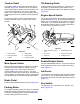
Figure12
1.Lynchpinandwasher
B.Insertthelift-armyokeontothecarrier-frame
shaft(Figure11).
C.Insertthelift-armshaftintotheliftarmand
secureitwiththewasherandlynchpin
(Figure12).
10.Insertthecapoverthecarrier-frameshaftand
lift-armyoke.
11.Securethecapandthecarrier-frameshafttothe
lift-armyokewiththesnapperpin(Figure10).
Note:Usetheslotifasteeringcuttingunitis
desiredorusetheholeifthecuttingunitistobe
lockedinposition
12.Securethelift-armchaintothechainbracket
withthesnapperpin(Figure13).
Note:Usethenumberofchainlinksdescribed
intheOperator'sManualforthecuttingunit.
g003948
Figure13
1.Lift-armchain
3.Pin
2.Chainbracket
13.Oncuttingunit4(leftfront)andcuttingunit5
(rightfront),insertthereel-motorhosesintothe
respectivehoseguide.
14.Coatthesplineshaftofthereelmotorwithclean
grease.
15.Oilthereel-motorO-ringandinstallitontothe
motorange.
16.Installthemotorbyrotatingitclockwisesothat
themotorangesclearthebolts(Figure14).
Note:Rotatethemotorcounterclockwiseuntil
theangesencircletheboltsandthentighten
thebolts.
Important:Makesurethatthereel-motor
hosesarenottwisted,kinked,oratriskof
beingpinched.
g004127
Figure14
1.Reel-drivemotor2.Mountingbolts
13