
Service Manual


Piston(Traction)PumpControlAssembly
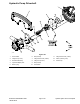
g213707
Figure145
1.Locknut
10.Flange-headscrew(2each)
19.Tractionneutralswitch
2.Pumplever
11.Guardhoop20.Jamnut(2each)
3.Locknut
12.Flangenut(2each)21.Lockwasher(2each)
4.Bolt(3each)13.Piston(traction)pump
22.Retainingring
5.Pumpplate14.Flangenut23.Leverdamper
6.Cablerodend
15.Tractioncablebracket24.Bolt
7.Flatwasher
16.Flange-headscrew(2each)25.Carriagescrew
8.Flatwasher17.Tractioncontrolcable
9.Bolt18.Flangenut
DisassemblingthePiston(Traction)PumpControlAssembly
1.Parkthemachineonalevelsurface,settheparkingbrake,lowerthecutting
units,andshutofftheengine,andremovethekeyfromthekeyswitch.
2.Removethecomponentsfromthetractionpumpcontrolassemblyas
necessary(Figure145andFigure146).
HydraulicSystem:ServiceandRepairs
Page6–156
Reelmaster
®
5410/5510/5610Series
15216SLRevD