
Service Manual


DisassemblingtheBrake(continued)
5.Removethebrakereturnspring(item19inFigure295)andclevispinthat
attachthebrakecabletothebrakeactuatorlever.
6.Removethebrakedrum(item14inFigure295)fromthebrakeassembly.
IMPORTANT
Donothitthewheelhub,wheel-hubpuller,orwheelmotorwitha
hammerwhileremovingorinstallingthewheelhub.Hammeringcan
damagethewheelmotor.
7.Ensurethatthelocknut(item15inFigure295)onthewheelmotorshaftis
loosenedatleastto2turns.Useahubpuller(refertoSpecialT ools(page
8–4))toloosenthewheelhubfromthewheelmotorshaft.
8.Removethelocknutandwheelhubfromthemotorshaft.Discardthelocknut.
Locateandretrievethesquarekey.
Note:Ifnecessary,thecompletebrakeassemblycanberemovedfromthe
machinefordisassembly(refertostep12).
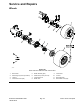
g185919
Figure296
1.Hold-downpin(2each)6.Brakeshoe(2each)
11.Brakeactuator
2.Backingplate
7.Shoespring
12.Brakeactuatorlever
3.Rivet(4each)8.Hold-downspring(2each)
13.Back-upplate
4.Clevispin9.Hold-downcup(2each)
14.Boot
5.Retainingring
10.Shoespring(actuator)
9.Removethe2shoesprings(items10and7inFigure296)fromthebrake
shoes.
10.Removethe2hold-downcups(item9inFigure296)and2hold-down
springs.
11.Removethe2brakeshoes(item6inFigure296)and2hold-downpins
fromthebackingplate.
12.Ifnecessary,removethe4bolts(item10inFigure295)toremovethebrake
backingplatefromthebrakeadapter.
AssemblingtheBrake
1.Useawirebrushtoremoverustandunwantedmaterialfromallthebrake
partsbeforetheinstallation.Cleanalltheparts.
Reelmaster
®
5410/5510/5610Series
Page8–11
Chassis:ServiceandRepairs
15216SLRevD