
Service Manual


AssemblingtheRoller(continued)
g252750
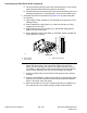
Figure361
1.Rollertube4.Bearing
2.Rollershaft5.Outerseal
3.Innerseal
6.Bearing/outersealtool
D.Carefullyinstalltherstoutersealintotherollertubeandensurethatthe
seallip(andgarterspring)facesendofthetube.Useabearing/outerseal
toolandasoft-facedhammertolightlyseatseal;referto(page).Ensure
thattheshaftandbearingsstillfreelyrotateafterthesealinstallation.
E.Usingthesameprocess,installthesecondoutersealandmakesure
nottocrushtheinstalledouterseal.Again,ensurethattheshaftand
bearingsstillfreelyrotate.
IMPORTANT
Ensurethatallgreaseisremovedfromtheshaftthreadstoprevent
thelooseningofthebearinglocknut.
5.Cleanthethreadsonbothendsoftherollershaft.
Note:Iforiginalbearinglocknut(s)arebeingused,applytheLoctite#243(or
equivalent)tothethreadsofthelocknut(s).
6.Installthebearinglocknutontoeachendoftherollershaft.Ensurethatthe
outersealsarenotdamagedduringthenutinstallation.Torquethelocknutto
68to81N∙m(50to60ft-lb).
7.Aftertherollerisinstalledtothecuttingdeck,lubricatetherollergrease
ttings,rotatetherollertoproperlydistributegreaseinbearingsandclean
excessgreasefromtherollerends.Aproperlyassembledrollershouldrotate
withlessthan0.68N∙m(5in-lb)resistance.
Reelmaster
®
5410/5510/5610Series
Page9–55
CuttingUnit:ServiceandRepairs
15216SLRevD