
Service Manual


RemovingtheReelAssembly(continued)
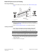
g230064
Figure342
1.Carrierframe
5.Flatwasher9.LHsideplate
2.Shim(ifequipped)6.Capscrew10.Socket-headscrew
3.Supporttube
7.Flange-headscrew11.Flangenut
4.Framespacer8.Reargrassshield
8.Removetheboltandatwasherthatsecurethereargrassshieldtothe
LHsideplate.
9.Removeangeheadscrewthatsecuressupporttube,framespacerand
carrierframetoLHsideplate
Note:Thereelbearingsandsealsarepresstonthecuttingreelshaftand
shouldremainonthereelwhenremovingtheLHsideplate.
Note:Sideplateson5”cuttingunitsattachtocuttingunitframewithtwo(2)
shoulderboltsandangenuts.Sideplateson7”cuttingunitsusethree
(3)shoulderboltsandangenuts.
10.Removeshoulderbolts(item7)andangenutsthatsecuretheLHside
platetothecuttingunitframe.RemovetheLHsideplatefromthereelshaft,
rollers,bedbarassemblyandcuttingunitframe.
CAUTION
Contactwiththereel,bedknife,orothercuttingunitpartscanresult
inpersonalinjury.
Useheavygloveswhenremovingthecuttingreel.
11.CarefullypullthecuttingreelwiththebearingsandsealsfromtheRHside
plate.
CuttingUnit:ServiceandRepairs
Page9–32
Reelmaster
®
5410/5510/5610Series
15216SLRevD