
Service Manual


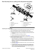


Table Of Contents
- Title Page
- Revision History
- Reader Comments
- NOTES:
- Preface
- Table of Contents
- Chapter 1 : Safety
- Chapter 2 : Specifications and Maintenance
- Specifications
- Torque Specifications
- Identifying the Fastener
- Fasteners with a Locking Feature
- Calculating the Torque Values When Using a Drive-Adapter Wrench
- Standard Torque for Dry, Zinc Plated, and Steel Fasteners (Inch Series)
- Standard Torque for Dry, Zinc Plated, and Steel Fasteners (Metric Fasteners)
- Other Torque Specifications
- Conversion Factors
- Shop Supplies
- Special Tools
- Chapter 3 : Kubota Diesel Engine
- Chapter 4 : Yanmar Diesel Engine
- Chapter 5 : Kubota Gasoline Engine
- Chapter 6 : Hydraulic System
- 1 Specifications
- General Information
- Checking the Hydraulic Fluid
- Pushing or Towing the Traction Unit
- Releasing Pressure from the Hydraulic System
- Traction Circuit Component Failure
- Hydraulic Hoses
- Installing the Hydraulic Hose and Tube (O-Ring Face Seal Fitting)
- Installing the Hydraulic Fittings (SAE Straight Thread O-Ring Fitting into the Component Port)
- Hydraulic Schematics
- Hydraulic Flow Diagrams (5410/5410-D/5510/5510-D/5610)
- Hydraulic Flow Diagrams (5610-D)
- Special Tools
- Troubleshooting
- Testing the Hydraulic System
- Traction Circuit Relief Valve (R3) and (R4) Pressure Test (5410/5410-G/5410-D/5510/5510-G/5510-D/5610)
- Traction Circuit Charge Pressure Test (5410/5410-G/5410-D/5510/5510-G/5510-D/5610)
- Gear Pump (P3) Flow Test (Using Tester with Flow Meter and Pressure Gauge) (5410/5410-G/5410-D/5510/5510-G/5510-D/5610)
- Front Wheel Motor Efficiency Test (5410/5410-G/5410-D/5510/5510-G/5510-D/5610)
- Piston (Traction) Pump Flow Test (Using Tester with Flow Meter and Pressure Gauge) (5410/5410-G/5410-D/5510/5510-G/5510-D/5610)
- Relief Valve (R1) and (R2) Pressure Test (Cutting (Mow) Circuit) (5410/5410-G/5410-D/5510/5510-G/5510-D/5610)
- Gear Pump (P1) and (P2) Flow Test (Using Tester with Flow Meter and Pressure Gauge) (5410/5410-G/5410-D/5510/5510-G/5510-D/5610)
- Cutting Reel Motor Efficiency Test (Using Tester with Flow Meter and Pressure Gauge) (5410/5410-G/5410-D/5510/5510-G/5510-D/5610)
- Cutting Reel Motor Cross-Over Relief Pressure Test (5510/5510-G/5510-D/5610)
- Lift Relief Valve (SVRV) Pressure Test (5410/5410-G/5410-D/5510/5510-G/5510-D/5610)
- Gear Pump (P4) Flow Test (Using Tester with Flow Meter and Pressure Gauge) (5410/5410-G/5410-D/5510/5510-G/5510-D/5610)
- Lift Cylinder Internal Leakage Test (5410/5410-G/5410-D/5510/5510-G/5510-D/5610)
- Steering Relief Valve (R10) Pressure Test (5410/5410-G/5410-D/5510/5510-G/5510-D/5610)
- Steering Cylinder Internal Leakage Test (5410/5410-G/5410-D/5510/5510-G/5510-D/5610)
- Testing the Traction Circuit–Charge Pressure (5610-D)
- Testing the Traction Circuit–Wheel Motor Efficiency (5610-D)
- Testing the Traction Circuit–Piston Pump/Hydrostat Flow and Relief Pressure (5610-D)
- Testing the Mow Circuit–Circuit Pressure (5610-D)
- Testing the Mow Circuit–Reel Motor Efficiency/Case Drain (5610-D)
- Testing the Mow Circuit–Reel Motor Cross−Over Relief Pressure (5610-D)
- Testing the Mow Circuit–Relief Valve (RV1) and (RV2) Pressure (5610-D)
- Testing the Mow Circuit–Gear Pump (P1) and (P2) Flow (5610-D)
- Testing the Steering Circuit–Steering Control Valve, Relief Valve (R10) Pressure, and Steering Cylinder (5610-D)
- Testing the Steering Circuit–Gear Pump (P3) Flow (5610-D)
- Testing the lift Circuit–Relief Valve (SVRV) Pressure (5610-D)
- Testing the Lift Circuit–Lift Cylinder Internal Leakage (5610-D)
- Testing the Lift Circuit–Gear Pump (P4) Flow (5610-D)
- Service and Repairs
- General Precautions for Removing and Installing the Hydraulic System Components
- Checking the Hydraulic Lines and Hoses
- Priming the Hydraulic Pumps
- Flushing the Hydraulic System
- Filtering the Closed-Loop Traction Circuit
- Charging the Hydraulic System
- Hydraulic Tank
- Piston (Traction) Pump Control Assembly
- Hydraulic Pump Driveshaft
- Hydraulic Pump Assembly
- Servicing the Piston (Traction) Pump
- Servicing the Gear Pump
- Front Wheel Motors
- Servicing the Front Wheel Motor
- Rear Wheel Motors (Machine with CrossTrax AWD)
- Servicing the Rear Wheel Motor (Machine with CrossTrax AWD)
- CrossTrax™ AWD Control Manifold Assembly
- Servicing the CrossTrax AWD Control Manifold Assembly
- Mow Control Manifold Assembly
- Servicing the Mow Control Manifold Assembly
- Lift Control Manifold
- Servicing the Lift Control Manifold
- Servicing a Control Manifold Cartridge Valve
- Cutting Reel Motor
- Servicing the Cutting Reel Motor (Casappa)
- Servicing the Cutting Reel Motor (Sauer-Danfoss)
- Lift Cylinder
- Servicing the Lift Cylinder
- Steering Control Valve
- Servicing the Steering Control Valve
- Steering Cylinder
- Servicing the Steering Cylinder
- Oil Cooler (5410/5510/5610)
- Radiator and Oil Cooler Assembly (5410-G/5410-D/5510-G/5510-D/5610-D)
- Chapter 7 : Electrical System
- General Information
- Special Tools
- InfoCenter Display
- Troubleshooting
- Electrical System Quick Checks
- Adjustments
- Testing the Electrical Components
- Fusible Link Harness (Machines with Kubota or Yanmar Diesel Engine)
- System Fuses
- Engine Fuses (Gasoline Engine)
- Toro Electronic Controller (TEC)
- Key Switch
- Reel Engage Switch
- Engine Speed Switch (If Equipped)
- Lower/Raise Joystick Switches
- Headlight Switch
- Seat Switch
- Cutting Unit Down Limit Switch
- Traction Neutral Switch
- Parking Brake Switch
- Mow/Transport Switch
- Backlap Switches
- Oil Pressure Switch (Machine with Kubota Engine)
- Relays with 4 Terminals
- Relays with 5 Terminals (Diesel Engine)
- Engine Relays with 5 Terminals (Gasoline Engine)
- Hydraulic Solenoid Valve Coils
- Temperature Sender (Machine with Kubota Diesel Engine)
- Engine Run Solenoid (Machine with Kubota Diesel Engine)
- Fuel Sender (Diesel Engine)
- Fuel Sender (Gasoline Engine)
- Fuel Pump (Machine with Yanmar Diesel Engine)
- Fuel Pump (Machine with Kubota Diesel Engine)
- Fuel Pump (Machine with Kubota Gasoline Engine)
- CAN-bus Terminator Resistor
- Resistor Assembly (Machine with Yanmar Diesel or Kubota Gasoline Engine)
- Diode Assemblies (Diesel Engine)
- Service and Repairs
- Chapter 8 : Chassis
- Chapter 9 : Cutting Unit
- 1 Specifications
- General Information
- Special Tools
- Aftercut Appearance
- Adjustments
- Service and Repairs
- Hydraulic Reel Motor
- Backlapping
- Bedbar Assembly
- Bedknife Replacement and Grinding
- Servicing the Bedbar Adjuster
- Reel Assembly (cutting units with painted side plates)
- Reel Assembly Service (cutting units with painted side plates)
- Reel Assembly (cutting units with aluminum side plates)
- Reel Assembly Service (cutting units with aluminum side plates)
- Preparing the Reel for Grinding
- Front Roller
- Rear Roller
- Servicing the Roller
- Rear Roller Brush – Optional (cutting units with painted side plates)
- Rear Roller Brush – Optional (cutting units with aluminum side plates)
- Chapter 10 : Belt Driven Groomer (Optional)
- Chapter 11 : Universal Groomer (Optional)
- Appendix A: Foldout Drawings
- Electrical Drawing Designations
- Hydraulic Schematic-5410/5410-D
- Hydraulic Schematic-5510/5510-D/5610
- Hydraulic Schematic-5610-D
- Electrical Schematic-5410/5510/5610 (Models with Kubota Diesel Engine) (Serial Numbers Below 403430000)
- Electrical Schematic-5410/5510/5610 (Models with Kubota Diesel Engine) (Serial Numbers Above 403430000)
- Electrical Schematic-5410-D/5510-D/5610-D (Models with Yanmar Diesel Engine) (Serial Numbers Below 403430000)
- Electrical Schematic-5410-D/5510-D/5610-D (Models with Yanmar Diesel Engine) (Serial Numbers Above 403430000)
- NO TITLE
- Electrical Schematic-5410-G/5510-G (Models with Kubota Gasoline Engine)
- Wire Harness Drawing-Main (Serial Number Below 403430000)
- Wire Harness Drawing-Main (Serial Number Below 403430000)
- Wire Harness Drawing-Main (Serial Numbers 403430001 to 405680000)
- Wire Harness Drawing-Main (Serial Numbers 403430001 to 405680000)
- Wire Harness Drawing-Main (Serial Numbers Above 405680001)
- Wire Harness Drawing-Main (Serial Numbers Above 405680001)
- Wire Harness Drawing-Seat
- Wire Harness Drawing-Seat
- Engine Wire Harness Drawing-5410/5510/5610 (Models with Kubota Diesel Engine)
- Engine Wire Harness Diagram-5410/5510/5610 (Models with Kubota Diesel Engine)
- Engine Wire Harness Drawing-5410-D/5510-D (Models 03672 and 03687 with Yanmar Diesel Engine)
- Engine Wire Harness Diagram-5410-D/5510-D (Models 03672 and 03687 with Yanmar Diesel Engine)
- Engine Wire Harness Drawing-5410-D/5510-D/5610-D (Models 03606, 03607, and 03679)
- Engine Wire Harness Diagram-5410-D/5510-D/5610-D (Models 03606, 03607, and 03679)
- Engine Wire Harness Drawing-5410-G/5510-G (Models with Kubota Gasoline Engine)
- Engine Wire Harness Diagram-5410-G/5510-G (Models with Kubota Gasoline Engine)

RemovingtheReelAssembly(continued)
12.Inspectandservicethecuttingreelassemblyasnecessary;refertoReel
AssemblyService(cuttingunitswithpaintedsideplates)(page9–36).
InstallingtheReelAssembly
1.Cleanthesideplatesandothercuttingunitcomponents.Inspecttheside
platesforwearordamageandreplaceifnecessary.
Note:Checkthatthegreasesealsonthecuttingreelshaftareushto1.5
mm(0.060inch)awayfromtheretainingringonthereelshaft.Ifnecessary,
adjustthepositionofthegreasesealsforproperclearance.
2.Makesurethatgreasesealsandbearingsareproperlygreasedand
positionedoncuttingreel(seeReelAssemblyServiceinthissection).Apply
thincoatofgreasetooutsideofgreasesealsandbearingsoncuttingreel
toeasereelinstallation.Also,applygreasetobearingboresandthreadsin
sideplates.
CAUTION
Contactwiththereel,bedknife,orothercuttingunitpartscanresult
inpersonalinjury.
Useheavygloveswheninstallingthecuttingreel.
IMPORTANT
Duringcuttingreelinstallation,keepinnerandouterbearingraces
aligned.Ifbearingracesarenotaligned,bindingwilloccurandreel
installationmaycausebearingdamage.Usereelbearinginstallation
tool(Toropartnumber117-0975)tohelpwithbearingalignment
duringreelinstallation.
3.Usingreelbearinginstallationtooltokeepreelbearingaligned,carefullyslide
thecuttingreelwithbearingsandgreasesealsintotheRHsideplate;referto
(page).Makesurethatbearingisfullyseatedintosideplate.
4.OntheLHsideplate,loosenthesetscrew(item20)andback-off(loosen)
thebearingadjusternut1completeturn.
5.SlidetheLHsideplateontothecuttingreelassembly,frontrollerandrear
roller.MakesurethatreelendinRHsideplatedoesnotshiftinposition.
6.Installtheshoulderbolts(item7)andangenutsthatsecuretheLHside
platetothecuttingunitframe;tightentheshoulderboltsfrom37to44N∙m
(27to33ft-lb).
7.ApplyLoctite#243(orequivalent)tothreadsofangeheadscrewthat
securessupporttube,framespacerandcarrierframetoLHsideplate.Install
screwandtorquefrom37to44N∙m(27to33ft‐ ‐
‐
lbs).Aftertighteningscrew,
checktheclearancebetweenthecarrierframeandsideplate.Ifclearance
ismorethan2.3mm(0.090inch),removeangeheadscrewandposition
shim(s)(partnumber67-9410)betweencarrierframeandsideplatesothat
clearanceislessthan2.3mm(0.090inch).Makesurethatthecarrierframe
pivotsfreelyafterassembly.
8.InstallcapscrewandatwasherthatsecurereargrassshieldtoLHside
plate.Tightenscrewfrom20to25N∙m(15to19ft‐ ‐
‐
lbs).
Reelmaster
®
5410/5510/5610Series
Page9–33
CuttingUnit:ServiceandRepairs
15216SLRevE