
Operator's Manual


B.Inserttheliftarmyokeontothecarrierframe
shaft(Figure11).
C.Inserttheliftarmshaftintotheliftarmandsecure
itwiththewasherandlynchpin(Figure12).
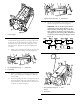
10.Insertthecapoverthecarrierframeshaftandliftarm
yoke.
11.Securethecapandthecarrierframeshafttothelift
armyokewiththesnapperpin.Usetheslotifasteering
cuttingunitisdesiredorusetheholeifthecuttingunit
istobelockedinposition(Figure10).
12.Securetheliftarmchaintothechainbracketwiththe
snapperpin(Figure13).Usethenumberofchainlinks
describedinthecuttingunitOperator'sManual.
Figure13
1.Liftarmchain2.Chainbracket
13.Onthe#4(leftfront)and#5(rightfront)cutting
units,insertthereelmotorhosesintotherespective
hoseguide.
14.Coatthesplineshaftofthereelmotorwithclean
grease.
15.OilthereelmotorO-ringandinstallitontothemotor
ange.
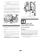
16.Installthemotorbyrotatingitclockwisesothatthe
motorangesclearthebolts(Figure14).Rotatethe
motorcounterclockwiseuntiltheangesencirclethe
boltsthentightenthebolts.
Important:Makesurethereelmotorhosesare
nottwisted,kinkedorintheriskofbeingpinched.
Figure14
1.Reeldrivemotor2.Mountingbolts
5
AdjustingtheTurf
CompensationSpring
NoPartsRequired
Procedure
Theturfcompensationspring(Figure15)transfersweight
fromthefronttotherearroller.(Thishelpstoreduceawave
patternintheturf,alsoknownasmarcellingorbobbing.)
Important:Makespringadjustmentswiththecutting
unitmountedtothetractionunit,pointingstraight
aheadandloweredtotheshopoor.
1.Makesurethehairpincotterisinstalledintherearhole
inthespringrod(Figure15).
14