
Service Manual


Reelmaster 5010 Series
DPA Cutting Units
Page 7 − 31
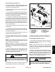
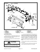
1. Frame
2. LH side plate
3. RH side plate
4. Shoulder bolt (4)
5. Carrier frame
6. Flange head screw (2)
7. Flange bushing (2)
8. Rear grass shield
9. Spacer (2)
10. Shim (0.060” − as required)
11. Flange nut (2)
12. Flange nut (4)
13. Special screw
14. Flat washer
15. Cap screw
16. Shim (as required)
Figure 37
15 to 19 ft−lb
(20 to 25 N−m)
27 to 33 ft−lb
(37 to 44 N−m)
1
2
3
4
4
5
6
7
7
8
9
9
16
10
11
12
12
11
13
14
15
27 to 33 ft−lb
(37 to 44 N−m)
27 to 33 ft−lb
(37 to 44 N−m)
15 to 19 ft−lb
(20 to 25 N−m)
16
Reel Assembly Removal
1. Position machine on a clean and level surface, lower
cutting units, stop engine, engage parking brake and re-
move key from the ignition switch.
2. Remove the cutting unit from the machine and place
on a flat work area.
CAUTION
Contact with the reel, bedknife or other cutting
unit parts can result in personal injury. Use
heavy gloves when removing the cutting reel.
3. If cutting unit is equipped with a counterweight or ac-
cessory on LH side plate, remove the counter weight or
accessory from the cutting unit. Remove and discard
O−ring from counter weight. See Chapter 8 − Belt Driven
Groomer or Chapter 9 − Universal Groomer in this
manual for additional Groomer information. See Rear
Roller Brush in this chapter for information on rear roller
brush.
4. Remove bedbar assembly (see Bedbar Assembly in
this chapter).
5. Remove front and rear rollers (see Front Roller Re-
moval and Rear Roller Removal in this chapter).