
Service Manual


ServicingtheGroomerReel
g220506
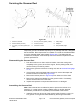
Figure408
1.Groomerreelshaft4.6.3mm(1/4inch)spacer(2each)7.Sharpedge
2.Groomerblade(40each)5.Locknut(2each)
8.Midpoint
3.31.7mm(1–1/4inch)spacer(39
each)
6.Centeredonshaft9.Dull(rounded)edge
Inspectthegroomerreelbladesfrequentlyforanydamageandwear.Straighten
thebentblades.Eitherreplacethewornbladesorreversetheindividualblades
toputthesharpestbladeedgeforward(Figure408).Thebladesthatare
roundedtothemidpointofthebladetipmustbereversedorreplacedforbest
groomerperformance.
DisassemblingtheGroomerReel
1.Parkthemachineonacleanandlevelsurface,lowerthecuttingunits
completelytotheground,shutofftheengine,settheparkingbrake,and
removethekeyfromthekeyswitch.
2.Removethegroomerreelfromthecuttingunit;refertoGroomerReel(page
11–17).
3.Ifthegroomerreelisequippedwithbroomerkit,removethestrapsand
broomerbrushesfromthereel(Figure409).
4.Removethelocknut(item5inFigure408)fromeitherendoftheshaft.
5.Removethespacersandbladesfromthegroomershaft.Ifnecessary,
removesecondlocknutfromtheshaft.
6.Inspectandreplacethecomponentsthatarewornordamaged.
AssemblingtheGroomerReel
Note:Newlocknutshaveanadhesivepatchtopreventthelocknutfrom
loosening.Ifausedlocknutisbeinginstalled,applyamediumstrength
threadlocker(Loctite#243orequivalent)tothethreadsofthelocknut.
1.Installthelocknutondriveendofthegroomershaft.Placea6.3mm(1/4
inch)spaceronthegroomershaftfollowedbytherstgroomerblade.
Reelmaster
®
5410/5510/5610Series
Page11–19
UniversalGroomer(Optional):ServiceandRepairs
15216SLRevD