
Service Manual


Front Axle Removal
1. Drain oil from transaxle.
2. Jack up front of machine and support chassis frame
wit
h jack stands.
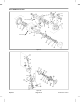
3. Remove front wheels. Remove nuts (Fig. 12,
Item 20). Use a puller to pull wheel hubs (Item 14) off of
shaft.
4. Clean all exterior surfaces of axle and transaxle.
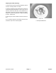
5. Disconnect hydraulic motor (Fig. 11, Item 27) from
transaxle. DO NOT disconnect hoses from hydraulic
motor.
6. Disconnect brake linkage rod eyes from brake link-
age
arms.
7. Disconnect and put covers on hydraulic lines that run
under axle assembly or that go through bulkhead brack-
ets connected to axle assembly. Mark hydraulic lines for
proper reassembly.
8. Support axle assembly, then remove U-bolts (Fig. 12,
Ite
m 25) securing axle to frame.
9. Carefully lower and pull axle assembly out from
unde
r machine.
Front Axle Disassembly
1. Remove skid plate (Fig. 12, Item 27).
NOTE: Before removing axle housings, scribe align-
ment
marks across transaxle housing, adapter plate
and axle housing for proper reassembly.
2. Remove remaining capscrews securing axle housing
(It
em 11) to transaxle and carefully pull axle housing and
shaft (Item 12) away from transaxle.
3. Remove axle housing cover (Item 7).
4. Remove cotter pin and clevis pin to disconnect brake
clevis from brake actuator.
5. Remove brake disks (Item 3) and brake actuator
(Item 4).
6. Remove adapter plate (Item 1) and transaxle spacer
(Item 38).
7. To remove axle from housing, remove retaining ring
(It
em 23) from outboard end of housing, then tap lightly
with a mallet from inside out. A pressed on, sealed ball
bear
ing (Item 24) will be on end of axle.
8. Do steps 2 - 7 for axle housing on other side.
Front Axle Assembly
Reverse steps 1 - 8 under Front Axle Disassembly.
IMPORTANT: Outboard axle support bearings
(Fig
. 12, Item 24) are a special design with a
“cracked race”. When bearing is installed, it is im-
portant that this crack points down. Improper instal-
lation will result in rapid bearing wear. Apply Loctite
680 or equivalent to outer race of bearing before
installing in axle housing.
To install axle assemblies into transaxle case, grease
axle
spline ends heavily. Push axle through seal. Use
caution to prevent damage to seal when axle splines
are going through seal.
Front Axle Installation
Reverse steps 1 - 9 under Front Axle Removal.
If a new transaxle is installed, determine correct shim to
use
behind spiral bevel gear on hydraulic motor by
subtracting actual motor flange face to sleeve dimen-
sion from dimension stamped on transaxle or attached
to tag.
Dimensional Range Pinion Shim
2.6000 - 2.6155 0.038 (82-5390)
2.6156 - 2.6225 0.045 (82-5380)
2.6226 - 2.6400 0.052 (82-5400)
After Assembly
1. Fill transaxle with approximately 144 oz. (4.5 U.S. qt.)
of
SAE 80-90W EP gear lube.
2. Check for hydraulic oil leaks.
3. Check adjustment of transaxle shift linkage.
4. Check brake “free play” adjustment.
Reelmaster
®
335-D Page 6 - 9 Repairs