
Operator's Manual


"
+)63'
'45 135
'45 135
'45 135 15 *180
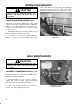
Test Port #2 is used to assist in trouble shooting
the hydraulic circuit for the rear cutting units.
Test Port #3 is located on the rear of the hydrostatic
transmission and is used to measure the charge
pressure of the transmission.
+)
The machine must not creep when traction pedal is
released. If it does creep, an adjustment is required.
Park machine on a level surface, shut engine off
and lower cutting units to the floor. Depress only the
right brake pedal and engage the parking brake.
Jack up left side of machine until front tire is off the
shop floor. Support machine with jack stands to
prevent it from falling accidentally.
: On 4 wheel drive models, left rear tire must also
be off the shop floor or 4 wheel drive driveshaft must be
removed.
Under right side of machine, loosen locknut on
traction adjustment cam.
+)63'
3#%5+10 &,645/'05 #/
!
0)+0' /645 $' 3600+0) 41 (+0#. #&,645/'05 1(
5*' 53#%5+10 #&,645/'05 %#/ %#0 $' 2'3:
(13/'& 1 )6#3& #)#+045 2144+$.' 2'3410#.
+0,639 -''2 *#0&4 (''5 (#%' #0& 15*'3 2#354 1(
5*' $1&9 #8#9 (31/ 5*' /6((.'3 15*'3 *15 2#354
1( 5*' '0)+0' #0& 15*'3 315#5+0) 2#354
Start engine and rotate cam hex in either direction
until wheel ceases rotation.
Tighten locknut securing adjustment.
Stop the engine and release the right brake.
Remove jack stands and lower the machine to the
shop floor. Test drive the machine to make sure it does
not creep.
+)
The cutting unit lift circuit is equipped with (3)
adjustable valves used to ensure the cutting units do
not raise too quickly and bang against lift stops. Adjust
cutting units as follows:
'05'3 655+0) 0+5
Locate valve behind access panel above
operator's platform.
. Loosen setscrew on valve and rotate valve
approximately 1/2 turn clockwise.
Verify lift rate adjustment by raising and lowering
cutting unit several times. Readjust as required.
After desired lift rate is attained, tighten setscrew to
lock adjustment.
+)63'
'05'3 %655+0) 60+5 #&,645/'05 7#.7'
654+&' 3105 655+0) 0+54
Locate valve on left front lift cylinder (under foot
rest).
Loosen setscrew on valve. Rotate valve 1/2 turn
clockwise.
Verify lift rate adjustment by raising and lowering
cutting units several times. Readjust as required.
After desired lift rate is attained, tighten set screw
to lock adjustment.