
Operator's Manual


!
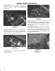
Pump lever on fuel pump (Fig. 31) until a solid
stream of fuel flows out around screw on fuel injection
pump. Tighten air bleed screw.
04' 02.#--8 '/)+/' 3*05-& 34#24 #(4'2 #$06'
$-''&+/) 120%'&52'3 #2' (0--07'& 07'6'2 +(
'/)+/' &0'3 /04 34#24 #+2 .#8 $' 42#11'& $'47''/
+/,'%4+0/ 15.1 #/& +/,'%4023 2'('2 40 -''&+/) +2
20. /,'%4023
+)
To achieve a consistent, high quality-of-cut and a
uniform after cut appearance, it is important that the
reel speed controls (located under seat) be correctly
set.
Adjust the reel speed controls as follows:
Select the height-of-cut at which the cutting
units are set.
Choose the desired ground speed best suited for
conditions.
Using the appropriate graph (See graph figure 33)
for 5 blade or 8 blade cutting units, determine the
proper reel speed setting.
+)52'
To set reel speed, rotate knobs (Fig. 34) until
indicator arrows are in line with the number
designating desired setting.
+)52'
''- 1''& 0/420- /0$3
04' Reel speed can be increased or decreased to
compensate for turf conditions.
! " !
+)
The down pressure spring on each cutting unit lift arm
can be adjusted to compensate for different turf
conditions. Increased down pressure will help keep
the cutting units on the ground when mowing at higher
speeds and helps maintain a uniform height-of-cut in
rough conditions or in areas of thatch build up.
Each down pressure spring may be adjusted to one of
four settings. Each increment increases or decreases
down pressure on cutting unit by 8 lbs.
Position machine on a level surface, lower the
cutting units, stop the engine, engage the parking
brakes and remove key from ignition switch.
Remove floor plate in front of seat and open the
hood to gain access to all (5) springs.
!
12+/)3 #2' 5/&'2 4'/3+0/ 53' %#54+0/ 7*'/
#&,534+/)
Place an open end wrench on the hex shaft of the
spring bracket.