
Service Manual


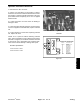


Table Of Contents
3
Backlap Switch
The Backlap switch is a three-way switch (Fig. 17). Test
the switch by disconnecting the wires and connecting a
continuity tester across terminals of switch.
With the switch OFF, the tester should show no continu-
i
ty across terminals 4 – 5 or 5 – 6.
With the switch in the FRONT position (toward keyway),
tester should show continuity across terminals
4 and 5.
With the switch in the REAR position (away from key-
way),
tester should show continuity across terminals 5
and 6.
1
2
Terminals on switch Wire color
Figure 17
1 (Not used)
2 (
Not used)
1. Backlap switch 3. S
tart relay
3 (Not used)
2. Glow relay
4 Blue
5 Black
6 White
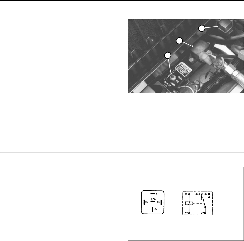
Start Relay
To test the start relay (Fig. 17), disconnect the relay wire
connector and install a continuity tester between the
relay terminals (terminals 30 and 87) (Fig. 18). The relay
should make and break continuity at terminals 30 and
87 as 12 V.D.C. is connected and disconnected to
terminal 85 with terminal 86 connected to ground.
Resistance specifications:
Terminals 85 and 86 = 80 to 90 Ohms
Terminals 30 and 87a (normally closed) = continuity
Terminals 30 and 87 (normally open) = continuity when 12V
DC is applied to terminals 85 and 86
Figure 18
Testing P
age 5 - 22
Rev. B
Reelmaster
®
5300-D