
Service Manual


Reelmaster 2000–DHydraulic System Page 4 – 80
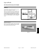
Oil Cooler
1. Oil cooler
2. Hydraulic connector
3. O–ring
4. Bulkhead nut
5. 90
o
hydraulic fitting
6. Hose clamp
7. Hydraulic hose (from manifold)
8. Knob
9. Lock nut
10. Protective sleeve
11. Hydraulic hose (to reservoir)
12. Nut
13. Front screen bracket
14. Flat washer
15. Lock nut
16. Flange head screw
17. Left front panel
Figure 58
FRONT
RIGHT
1
6
5
5
9
8
4
4
12
13
2
16
17
6
7
10
11
2
3
15
14
3
IN
OUT
Hydraulic
Sealant
Removal (Fig. 58)
1. Park machine on a level surface, lower cutting units,
stop engine, engage parking brake, and remove key
from the ignition switch.
2. Open and remove the hood (see Traction Unit Oper-
ator’s Manual). Remove the radiator screen.
3. Loosen hose clamps and remove both hydraulic
hoses from fittings on oil cooler. Allow hoses to drain oil
into a suitable container.
4. Remove 90
o
hydraulic fittings from oil cooler assem-
bly. Remove and discard o–rings from connectors.
5. Remove bulkhead nuts from oil cooler assembly.
6. Pull oil cooler from screen bracket.
7. If necessary, remove hydraulic connectors from oil
cooler.
Installation (Fig. 58)
1. If hydraulic connectors were removed, apply hydrau-
lic sealant to threads of connectors. Install connectors
to oil cooler. Coat new o–rings with hydraulic oil. Install
new o–rings in connectors.
2. Position and secure oil cooler to screen bracket with
bulkhead nuts.
3. Install 90
o
hydraulic fittings to oil cooler assembly.
Orientate top fitting straight back and bottom fitting 45
o
down.
4. Install hydraulic hoses to fittings and secure with
hose clamps.
5. Install hood on the machine.