
Service Manual


11
Front Lift Cylinder Service
9
7
5
3
10
8
1
6
4
2
12
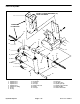
Figure 50
1. Retaining ring 5. O–ring
2. O–ring 6. Shaft
3. Head 7. O–ring
4. Backup washer 8. Piston
Disassembly (Fig. 50)
1. Remove oil from the cylinder into a drain pan by
slowly pumping the cylinder shaft (6). Plug both ports
and clean the outside of the lift cylinder
.
IMPORTANT: Prevent damage when clamping the
lift cylinder into a vise; clamp on the pivot only
. Do
not close vise enough to distort barrel.
2. Mount lift cylinder in a vise so that the shaft end tilts
up slightly
. Remove and discard dust seal (12).
3. Rotate head (3) with a spanner wrench and remove
retaining ring as shown in Figure 51.
4. Grasp end of shaft; extract shaft, head, and piston
(8) by carefully twisting and pulling on the shaft.
IMPORTANT: Do not clamp vise jaws against shaft
surface. Protect shaft surface before mounting in
vise.
9. Uni–ring
10. Lock nut
11. Barrel
12. Dust seal
5. Mount shaft securely in a vise by clamping vise on
the flats of the shaft. Remove locknut (10) and piston
from the shaft. Slide head from the shaft.
6. Remove and discard O–ring (7) and uni–ring (9) from
t
he piston. Remove and discard both O–rings (2 and 5)
and backup washer (4) from the head.
Spanner
wrench
Retaining
ring
Figure 51
Hydraulic System Page 4 – 70 Reelmaster 2000–D