
Service Manual


63.1 Rev. A
Reelmaster 2000--DHydraulic System Page 4 --
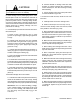
Hydraulic Manifold Service (Serial Number Above 290000000)
1. Handle assembly
2. Flow control cartridge (port FC)
3. #4 zero leak plug with O--ring
4. Orifice 0.076 (port OR2)
5. Orifice (port OR1)
6. Pilot directional element (port EP)
7. #6 zero leak plug with O--ring
8. Solenoid relief valve (port SV)
9. Solenoid coil
10. Nut
11. Backlap switch
12. Dowel pin
13. Ball
14. O--ring
15. #8 zero leak plug with O--ring
16. Spring pin
17. Retaining ring
18. Check valve
19. Back--up ring
20. Spool
21. O--ring
Figure 46.1
2
3
6
8
9
10
11
13
1
5
7
12
14
4
3
7
15
16
17
18
19
20
3
3
7
7
7
15
16
17
19
21
21
25 ft--lb
(34 N--m)
5 ft--lb
(6.7 N--m)
20 ft--lb
(27 N--m)
50 ft--lb
(67 N--m)
FRONT
UP
FRONT
UP
20 ft--lb
(27 N--m)
20 ft--lb
(27 N--m)
20 ft--lb
(27 N--m)
40 ft--lb
(54 N--m)
25 ft--lb
(34 N--m)
25 ft--lb
(34 N--m)
25 ft--lb
(34 N--m)
20 ft--lb
(27 N--m)
25 ft--lb
(34 N--m)
50 ft--lb
(67 N--m)
15 ft--lb
(20 N--m)
NOTE: The ports on the manifold are marked for easy
identification of components. Example: P1 is the gear
pump connection port and SV is the location for the sole-
noid cartridge (See Hydraulic Schematics to identify the
function of the hydraulic lines and cartridge valves at
each port).
NOTE: The hydraulic manifold shown in Figure 46.1
uses several zero leak plugs. These plugs have a ta-
pered sealing surface on the plug head that is designed
to resist vibration induced plug loosening. The zero leak
plugs also have an O--ring as a secondary seal. If zero
leak plug removal is necessary, lightly rap the plug head
using a punch and hammer before using an allen
wrench to remove the plug: the impact will allow plug re-
moval with less chance of damage to the socket head of
the plug.