
Operator's Manual


18
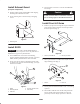
Mount Cutting Unit Drive
Motors
1. Position cutting units in front of lift arm pivot rods.
2. Remove weights and gasket (Fig. 18) from inside end of
right hand cutting unit. Remove plug from bearing
housing on outside end of right hand cutting unit and
install weights and gasket. Locate spider coupling
(Fig. 19) shipped in bearing housing.
1
2
Figure 18
1. Weights 2. Gasket
3. Remove shipping plug from bearing housings on
remaining cutting units (Fig. 14).
4. Insert O–ring (supplied with cutting unit) on flange of
drive motor.
5. Mount the motor and the spider coupling to the drive
end of the cutting unit and secure with two capscrews
provided with cutting unit.
1
2
3
Figure 19
1. Spider coupling
2. Reel motor
3. O–ring
Adjust Lift Arms
1. Start engine, raise lift arms and check to make sure
clearance between each lift arm and floor plate bracket
is .18” – .32” (Fig. 20). If clearance is not in this range,
back off stop bolts (Fig. 22) and adjust cylinder to attain
clearance. To adjust cylinder, back off the jam nut on
the cylinder (Fig. 21), remove pin from rod end and
rotate clevis. Install pin and check clearance. Repeat
procedure if required. Tighten clevis jam nut.
1
2
3
Figure 20
1. Lift arm
2. Floor plate bracket
3. Clearance
1
2
Figure 21
1. Front cylinder 2. Jam nut