
Operator's Manual


g353096
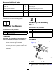
Figure18
1.Carriagebolt(3/8x1-1/4
inches)
4.Mountingplate(cutting
unit)
2.Plate(rearcarrierframe)5.Flangelocknut(3/8inch)
3.Spacer
2.Alignaspacerbetweenthecarrierplate
andmountingplate(Figure14),andloosely
assembletheplatesandspacerwithacarriage
bolt(3/8x1-1/4inches)andangelocknut(3/8
inch).
Note:Ifyouarestartingassemblyattheback
ofthecuttingunit,usethemiddleholesofeach
plate.
3.Repeatstep2attheotherplateholes.
4.Torquetheangelocknutsto37to45N∙m(27
to33ft-lb).
7
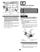
InstallingtheCuttingUnits
NoPartsRequired
Procedure
1.Slideathrustwasherontoeachfrontliftarm
pivotrod.
2.Slidethecuttingunitcarrierframeontothepivot
rodandsecureitwithalynchpin(Figure19).
Note:Onrearcuttingunit,positionthethrust
washerbetweentherearofthecarrierframe
andthelynchpin.
g012016
Figure19
1.Thrustwasher3.Lynchpin
2.Carrierframe
3.Greasealltheliftarmandcarrierframepivot
points.
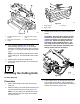
Important:Ensurethatthehosesarefree
oftwistsorsharpbendsandthattherear
cuttingunithosesareroutedasshowin
(Figure20).Raisethecuttingunitsand
shiftthemtotheleft(Model03171).The
rearcuttingunithosesmustnotcontact
thetractioncablebracket.Repositionthe
ttingsand/orhosesifnecessary.
g011965
Figure20
4.Routeatipperchainupthroughtheslotonthe
endofeachcarrierframe.Securethetipper
chaintothetopofthecarrierframewithabolt,a
washer,andalocknut(Figure21).
19