
Operator's Manual


g346440
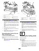
Figure14
1.Straightswiveltting
(returnhose)
2.90°swiveltting(lifthose)
3.Wraparagaroundthehosettings.
4.Slowlymovethelift-cylinderroduntilitaligns
withtheholesintherightlift-armanges(Figure
15).
Important:Somehydraulicuidisforced
outatthehosettingswhenyoumovethe
lift-cylinderrod.
g346439
Figure15
1.Greasetting4.Snapring
2.Liftarmange(right)5.Lift-cylinderrod
3.Mountingpin
6.Spacer
5.Assembletherodtotheangeswiththe
mountingpin,2spacers,and2snaprings
(Figure15).
6.ApplyNo.2lithiumgreasetothegreasettings
oftheliftarmandthehydrauliccylinder(Figure
15).
7.Torquetheswivelttingsofthereturnandlift
hosesto37to45N∙m(27to33ft-lb).
g346476
Figure16
1.Straightswiveltting
(returnhose)
2.90°swiveltting(lifthose)
8.Cleanhydraulicuidfromthemachine.
7
InstallingtheCarrier
FramestotheCuttingUnits
Partsneededforthisprocedure:
3
CuttingUnit(optionalpart—orderseparately)
PreparingtheCuttingUnits
1.Removethecuttingunitsfromthecartons.
2.Adjustthecuttingunitsasinstructedinthe
Operator’sManualforthecuttingunits.
InstalltheCarrierFramesforthe
FrontCuttingUnits
CuttingUnitwithLinks
Note:Thefrontcarrierframesarepartoftheoptional
liftarmkit.
1.Aligntheholesintheplatesofthefront-carrier
framewiththeholesinthecuttingunitmounting
plates(Figure17).
18