
Operator's Manual


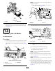


Table Of Contents
- NO TITLE
- .
- 1 Installing the Wheels
- 2 Installing the Steering Wheel
- 3 Activating, Charging, and Connecting the Battery
- 4 Checking the Angle Indicator
- 5 Installing the CE Decal
- 6 Installing the Hood Latch (CE Only)
- 7 Installing the Exhaust Guard (CE Only)
- 8 Installing the Roll Bar
- 9 Installing the Front Lift Arms
- 10 Installing the Carrier Frames to the Cutting Units
- 11 Mounting the Cutting Units
- 12 Mounting the Cutting Unit Drive Motors
- 13 Adjusting the Lift Arms
- 14 Installing the Tipper Roller Kit (Optional)
- NO TITLE
- NO TITLE
- Think Safety First
- Checking the Engine-Oil Level
- Filling the Fuel Tank
- Checking the Cooling System
- Checking the Hydraulic System
- Checking the Tire Pressure
- Checking the Reel-to-Bedknife Contact
- Torquing the Wheel Nuts
- Starting and Shutting Off the Engine
- Bleeding the Fuel System
- Checking the Interlock System
- Identifying the Tie-Down Points
- Hauling the Machine
- Towing the Machine
- Using the Standard Control Module (SCM)
- NO TITLE
- NO TITLE
- NO TITLE

ProductOverview
Controls
g008887
Figure31
1.Forwardtractionpedal4.Tiltsteeringlever
2.Reversetractionpedal5.Indicatorslot
3.Mow/transportslide
6.Angleindicator
TractionPedals
Pressthetractionforwardpedal(Figure31)tomoveforward.
Pressthetractionreversepedal(Figure31)tomovebackward
ortoassistinstoppingwhenmovingforward.Also,allowthe
pedaltomoveormoveittotheNEUTRALpositiontostop
themachine.
Mow/TransportSlide
Usingyourheel,movethemow/transportslide(Figure31)
tothelefttotransportandtotherighttomow .Thecutting
unitsoperateonlyinthemowposition.
Important:Themowspeedissetatthefactoryto9.7
km/h(6mph).Itcanbeincreasedordecreasedby
adjustingthespeedstopscrew(Figure32).
g008888
Figure32
1.Speedstopscrew
TiltSteeringLever
Pullthetiltsteeringlever(Figure31)backtoadjustthe
steeringwheeltothedesiredposition,thenpushthelever
forwardtotighten.
IndicatorSlot
Theslotintheoperatorplatform(Figure31)indicateswhen
thecuttingunitsareinthecenterposition.
AngleIndicator
Theangleindicator(Figure31)indicatesthesidehillangleof
themachineindegrees.
IgnitionSwitch
Theignitionswitch(Figure33),whichisusedtostart,stop,
andpreheattheengine,has3positions:OFF,ON/PREHEAT,
andSTART.RotatethekeytotheON/PREHEATposition
untiltheglowplugindicatorlightgoesout(approximately7
seconds);thenrotatethekeytotheSTARTpositiontoengage
thestartermotor.Releasethekeywhentheenginestarts.The
keyautomaticallymovestotheON/RUNposition.Toshut
offtheengine,rotatethekeytotheOFFpositionandremove
thekeyfromtheswitchtopreventaccidentalstarting.
g191213
Figure33
1.Throttle
7.Cutting-unitdriveswitch
2.Hourmeter
8.Cutting-unitshiftlever
3.Temperaturelight9.Ignitionswitch
4.Oil-pressurelight
10.Parkingbrake
5.Glow-plugindicatorlight11.Liftleverlock
6.Alternatorlight
Throttle
Movethethrottle(Figure33)forwardtoincreasetheengine
speedandrearwardtodecreasetheenginespeed.
26