
Operator's Manual


g011161
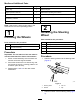
Figure10
1.Pivot-shaftlink2.Liftarmpivotshaft
AssemblingtheLiftArmstothe
Machine
1.Assembletheliftarmsontotheliftarmpivot
shaftsasshowninFigure11).
g346437
Figure11
1.Bolt(1/2x2inches)3.Liftarm
2.Pivot-shaftlink4.Liftarmpivotshaft
2.Assemblepivot-shaftlinktotheliftarmpivot
shafts(Figure11)withthe2angecapscrews
(1/2x2inches)thatyouremovedinPreparing
toInstalltheLiftArms(page16).
3.Torquethecapscrewsto95N∙m(70ft-lb).
AssemblingtheLiftCylinderto
theLeftLiftArm
Greasetype:No.2lithiumgrease
1.Alignthecapendoftheliftcylinderwiththe
holesintheleftlift-armanges(Figure12).
g346438
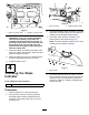
Figure12
1.Greasetting
4.Mountingpin
2.Liftarmange(left)5.Liftcylinder(capend)
3.Snapring
2.Assemblethecylindertotheangeswiththe
mountingpinand2snaprings(Figure12).
3.ApplyNo.2lithiumgreasetothegreasettings
oftheliftarmandthehydrauliccylinder(Figure
12).
AssemblingtheLiftCylinderto
theRightLiftArm
Greasetype:No.2lithiumgrease
1.Alignadrainpanbelowthehydraulicttingsof
theliftcylinder(Figure13).
g346441
Figure13
2.Attheliftcylinder,loosenthestraightswivel
ttingofthereturnhoseandthe90°swiveltting
ofthelifthose(Figure14).
17