
User's Manual


Clocks
Video Port2-12 SPRU629
2.4 Clocks
The video port has three external clock inputs as shown in Table 2–1. No
synchronization is required between the clocks sourced by the external pins.
VCLK1 and VCLK2 clock frequencies should be less than the DMA interface
clock. On 64x devices, the DMA interface clock is typically ½ the CPU clock
so this allows VCLK1 and VCLK2 to run at full frequency unless the 64x CPU
is running at less than 220 MHz. STCLK should be less than the peripheral bus
clock.
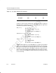
Table 2–1. Video Port Functional Clocks
Clock Source Frequency (MHz) Function
VCLK1 External pin 13.5–110 Clocks capture channel A and display logic and pin
side of the FIFOs.
VCLK2 External pin 13.5–80 Clocks capture channel B logic and FIFO pin side.
STCLK
External pin ~ 27 Clocks TSI system time counter and tick counter.
2.5 Video Port Functionality Subsets
The video port may be implemented with reduced features in low-cost devices.
2.5.1 Data Bus Width
The standard port has a 20-bit VDATA bus. Lower-cost implementations may
use a more narrow data bus at the expense of functionality. The following lists
the choices and their effect on the design:
- 20-bit – Full functionality.
- 10-bit – Single channel (channel A) only (DCDIS bit in VPSTAT always
set). Limits CMODE selection to 8/10-bit BT.656 and 8/10 bit raw capture
modes. Limits DMODE selection to 8/10-bit BT.656, and 8/10 bit raw
display. TSI capture mode may also be selected.
- 8-bit – Single channel (channel A) only (DCDIS bit in VPSTAT always set).
Limits CMODE selection to 8-bit BT.656 and 8-bit raw capture modes.
Limits DMODE selection to 8-bit BT.656 and 8-bit raw display. TSI capture
mode may also be selected.
Selection of 8-bit or 10-bit mode limits port operation to a single channel. This
selection also causes the removal of the channel B register file, channel B
filters and other logic, and ½ of the FIFO.
Clocks / Video Port Functionality Subsets