
User's Manual


GPIO Registers
5-19General Purpose I/O OperationSPRU629
5.1.9 Video Port Pin Interrupt Enable Register (PIEN)
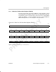
The video port pin interrupt enable register (PIEN) is shown in Figure 5–9 and
described in Table 5–10. The GPIOs can be used to generate DSP interrupts
or DMA events. The PIEN selects which pins may be used to generate an
interrupt. Only pins whose corresponding bits in PIEN are set may cause their
corresponding PISTAT bit to be set.
Interrupts are enabled on a GPIO pin when the corresponding bit in PIEN is
set, the pin is enabled for GPIO in PFUNC, and the pin is configured as an input
in PDIR.
Figure 5–9. Video Port Pin Interrupt Enable Register (PIEN)
31 24
Reserved
R-0
23 22 21 20 19 18 17 16
Reserved
PIEN22 PIEN21 PIEN20 PIEN19 PIEN18 PIEN17 PIEN16
R-0 R/W-0 R/W-0 R/W-0 R/W-0 R/W-0 R/W-0 R/W-0
15 14 13 12 11 10 9 8
PIEN15
PIEN14 PIEN13 PIEN12 PIEN11 PIEN10 PIEN9 PIEN8
R/W-0 R/W-0 R/W-0 R/W-0 R/W-0 R/W-0 R/W-0 R/W-0
76543210
PIEN7 PIEN6 PIEN5 PIEN4 PIEN3 PIEN2 PIEN1 PIEN0
R/W-0 R/W-0 R/W-0 R/W-0 R/W-0 R/W-0 R/W-0 R/W-0
Legend: R = Read only; R/W = Read/Write; -n = value after reset