
User's Manual


Video Port FIFO
Overview1-6 SPRU629
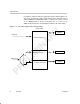
1.2.2 Video Capture FIFO Configurations
During video capture operation, the video port FIFO has one of four configura-
tions depending on the capture mode. For BT.656 operation, the FIFO is split
into channel A and B, as shown in Figure 1–2. Each FIFO is clocked indepen-
dently with the channel A FIFO receiving data from the VDIN[9–0] half of the
bus and the channel B FIFO receiving data from the VDIN[19–10] half of the
bus. Each channel’s FIFO is further split into Y, Cb, and Cr buffers with sepa-
rate write pointers and read registers (YSRCx, CBSRCx, and CRSRCx).
Figure 1–2. BT.656 Video Capture FIFO Configuration
VDIN[9–0]
VDIN[19–10]
Capture FIFO A
Y Buffer A (1280 bytes)
Cb Buffer A (640 bytes)
8/10
8/10
64
64
Cb Buffer B (640 bytes)
Cr Buffer B (640 bytes)
CRSRCB
CBSRCB
8/10
8/10
8/10
8/10
CBSRCA
64
64
64
Capture FIFO B
Cr Buffer A (640 bytes)
YSRCB
CRSRCA
64
YSRCA
Y Buffer B (1280 bytes)