
Datasheet


XIO2213B
www.ti.com
SCPS210F –OCTOBER 2008–REVISED MAY 2013
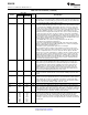
Table 2-10. Reserved Terminals
BALL NO.
SIGNAL I/O TYPE DESCRIPTION
ZAY ZAJ
PACKAGE PACKAGE
RSVD E12 F12 F13 K12 L12 L13 D11 E11 F12 J11 K10 K11 I/O Reserved, do not connect to external signals.
M11 M12 M13 N10 N11 N12 K12 L10 L11 L12 M05 M11
N13 P03 P10 P11 M12 N11 N12 N13
RSVD D12 D13 G12 M08 C10 D12 F11 M09 I Must be connected to V
SS
.
Table 2-11. Miscellaneous Terminals
BALL NO.
I/O
SIGNAL DESCRIPTION
ZAY ZAJ
TYPE
PACKAGE PACKAGE
GPIO0 P01 M02 I/O General-purpose I/O 0. This terminal functions as a GPIO controlled by bit 0
(GPIO0_DIR) in the GPIO control register (see Section 4.60).
Note: This terminal has an internal active pullup resistor.
GPIO1 N02 N01 I/O General-purpose I/O 1. This terminal functions as a GPIO controlled by bit 1
(GPIO1_DIR) in the GPIO control register (see Section 4.60).
Note: This terminal has an internal active pullup resistor.
GPIO2 P02 L02 I/O General-purpose I/O 2. This terminal functions as a GPIO controlled by bit 2
(GPIO2_DIR) in the GPIO control register (see Section 4.60).
Note: This terminal has an internal active pullup resistor.
GPIO3 N03 L04 I/O General-purpose I/O 3. This terminal functions as a GPIO controlled by bit 3
(GPIO3_DIR) in the GPIO control register (see Section 4.60).
Note: This terminal has an internal active pullup resistor.
GPIO4 N04 M03 I/O General-purpose I/O 4. This terminal functions as a GPIO controlled by bit 4
(GPIO4_DIR) in the GPIO control register (see Section 4.60).
Note: This terminal has an internal active pullup resistor.
GPIO5 P05 K04 I/O General-purpose I/O 5. This terminal functions as a GPIO controlled by bit 5
(GPIO5_DIR) in the GPIO control register (see Section 4.60).
Note: This terminal has an internal active pullup resistor.
GPIO6 P06 M06 I/O General-purpose I/O 6. This terminal functions as a GPIO controlled by bit 6
(GPIO6_DIR) in the GPIO control register (see Section 4.60).
Note: This terminal has an internal active pullup resistor.
GPIO7 N06 L05 I/O General-purpose I/O 7. This terminal functions as a GPIO controlled by bit 7
(GPIO7_DIR) in the GPIO control register (see Section 4.60).
Note: This terminal has an internal active pullup resistor.
OHCI_PME P08 M08 O OHCI power-management event. This is an optional signal that can be used by a
device to request a change in the device or system power state. This signal must be
enabled by software.
CYCLEOUT N08 L09 O Cycle out. This terminal provides an 8-kHz cycle timer synchronization signal. If not
implemented, this terminal should be left unconnected.
PD B03 B03 I Power down. A high on this terminal turns off all internal circuitry, except the cable-
active monitor circuits that control the CNA output. Asserting PD high also activates
an internal pulldown to force a reset of the internal control logic. If PD is not used,
this terminal must be connected to V
SS
.
GRST C13 C12 I Global power reset. This reset brings all of the XIO2213B internal link registers to
their default states. This should be a one-time power-on reset. This terminal has
hysteresis and an integrated pullup resistor.
SCL J13 G12 I/O Serial-bus clock. This signal is used as a serial bus clock when a pullup is detected
on SDA or when the SBDETECT bit is set in the serial bus control and status
register.
Note: This terminal has an internal active pullup resistor.
Copyright © 2008–2013, Texas Instruments Incorporated Overview 29
Submit Documentation Feedback
Product Folder Links: XIO2213B