
Datasheet


PCIR
XIO2001
www.ti.com
SCPS212G –MAY 2009–REVISED DECEMBER 2012
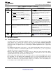
Table 3-3. Messages Supported by the Bridge (continued)
MESSAGE SUPPORTED BRIDGE ACTION
Set_Slot_Power_Limit Yes Received and processed
Unlock No Discarded
Hot plug messages No Discarded
Advanced switching messages No Discarded
Vendor defined type 0 No Unsupported request
Vendor defined type 1 No Discarded
All supported message transactions are processed per the PCI Express Base Specification.
3.4 PCI Bus Interface
3.4.1 I/O Characteristics
Figure 3-4 shows a 3-state bi-directional buffer that represents the I/O cell design for the PCI bus.
Section 7.7, Electrical Characteristics over Recommended Operating Conditions, provides the electrical
characteristics of the PCI bus I/O cell.
NOTE
The PCI bus interface on the bridge meets the ac specifications of the PCI Local Bus
Specification. Additionally, PCI bus terminals (input or I/O) must be held high or low to
prevent them from floating.
Figure 3-4. 3-State Bidirectional Buffer
3.4.2 Clamping Voltage
In the bridge, the PCI bus I/O drivers are powered from the V
DD_33
power rail. Plus, the I/O driver cell is
tolerant to input signals with 5-V peak-to-peak amplitudes.
For PCI bus interfaces operating at 50MHz or 66 MHz, all devices are required to output only 3.3-V peak-
to-peak signal amplitudes. For PCI bus interfaces operating at 25-MHz or 33-MHz, devices may output
either 3.3-V or 5-V peak-to-peak signal amplitudes. The bridge accommodates both signal amplitudes.
Each PCI bus I/O driver cell has a clamping diode connected to the internal V
CCP
voltage rail that protects
the cell from excessive input voltage. The internal V
CCP
rail is connected to two PCIR terminals. If the PCI
signaling is 3.3-V, then PCIR terminals are connected to a 3.3-V power supply via a 1kΩ resistor. If the
PCI signaling is 5-V, then the PCIR terminals are connected to a 5-V power supply via a 1kΩ resistor.
The PCI bus signals attached to the V
CCP
clamping voltage are identified as follows
• Table 2-5, PCI System Terminals, all terminal names except for PME
• Table 2-7, Miscellaneous Terminals, the terminal name SERIRQ.
3.4.3 PCI Bus Clock Run
The bridge supports the clock run protocol as specified in the PCI Mobile Design Guide. When the clock
run protocol is enabled, the bridge assumes the role of the central resource master.
Copyright © 2009–2012, Texas Instruments Incorporated Feature/Protocol Descriptions 27
Submit Documentation Feedback
Product Folder Links: XIO2001