
Datasheet


XIO2001
SCPS212G –MAY 2009–REVISED DECEMBER 2012
www.ti.com
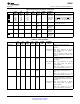
Table 2-6. JTAG Terminals (continued)
ZGU ZAJ PNP I/O CELL CLAMP EXTERNAL
SIGNAL DESCRIPTION
BALL # BALL # PIN # TYPE TYPE RAIL PARTS
JTAG_TRST L09 L09 60 I LV V
DD_33
JTAG test reset. This terminal provides
CMOS Optional for asynchronous initialization
of the TAP controller.
Note: This terminal has an internal
Optional pullup
active pullup resistor. The pullup is
resistor
active at all times.
Note: This terminal should be tied to
ground or pulled low if JTAG is not
required.
Table 2-7. Miscellaneous Terminals
ZGU ZAJ PNP I/O CELL CLAMP EXTERNAL
SIGNAL DESCRIPTION
BALL # BALL # PIN # TYPE TYPE RAIL PARTS
CLKRUN_ A13 C11 96 I LV V
DD_33
Clock run enable
Optional
EN CMOS
pullup/
0 = Clock run support disabled
pulldown
resistor
1 = Clock run support enabled
EXT_ARB_ C10 A12 97 I LV V
DD_33
Optional
External arbiter enable
EN CMOS
pullup/
0 = Internal arbiter enabled
pulldown
resistor
1 = External arbiter enabled
GPIO0 // N09 N09 55 I/O LV V
DD_33
General-purpose I/O 0/clock run. This terminal
CLKRUN CMOS
functions as a GPIO controlled by bit 0
(GPIO0_DIR) in the GPIO control register (see
Section 4.59) or the clock run terminal. This
terminal is used as clock run input when the
bridge is placed in clock run mode.
Optional
pullup
Note: In clock run mode, an external pullup
resistor
resistor is required to prevent the CLKRUN
signal from floating.
Note: This terminal has an internal active pullup
resistor. The pullup is only active when reset is
asserted or when the GPIO is configured as an
input.
GPIO1 // M09 M09 56 I/O LV V
DD_33
General-purpose I/O 1/power override. This
PWR_ CMOS
terminal functions as a GPIO controlled by bit 1
OVRD
(GPIO1_DIR) in the GPIO control register (see
Section 4.59) or the power override output
terminal. GPIO1 becomes PWR_OVRD when
bits 22:20 (POWER_OVRD) in the general
–
control register are set to 001b or 011b (see
Section 4.65).
Note: This terminal has an internal active pullup
resistor. The pullup is only active when reset is
asserted or when the GPIO is configured as an
input.
GPIO2 N10 N10 57 I/O LV V
DD_33
General-purpose I/O 2. This terminal functions
CMOS
as a GPIO controlled by bit 2 (GPIO2_DIR) in
the GPIO control register (see Section 4.59).
–
Note: This terminal has an internal active pullup
resistor. The pullup is only active when reset is
asserted or when the GPIO is configured as an
input.
20 Overview Copyright © 2009–2012, Texas Instruments Incorporated
Submit Documentation Feedback
Product Folder Links: XIO2001