
Datasheet


FOUR-QUADRANT MULTIPLIER DIFFERENCE AMPLIFIER
V =
OUT
´ V V +
G
´
IN
R
F
R
G
R
F
R
G
-
R
F
R
1
´ V
IN
(1)
V =
OUT
´ V V
IN
´
G
R
F
R
G
(2)
R
F
+V
IN
R
G+
R
G-
-V
IN
FB
R
G
R
2
R
3
20W
V
IN
V
G
R
S
Source
Impedance
R
1
VCA822
R
F
+V
IN
R
G+
R
G-
-V
IN
FB
R
G
R
S
R
S
20W
V
IN+
V
IN-
VCA822
95
90
40
Frequency(Hz)
Common-ModeRejectionRatio(dB)
100k 100M
85
45
75
80
10M1M
50
55
60
65
70
Input-Referred
1.5
1.0
-1.5
Time( s)m
Amplitude(V)
0 1 102
0.5
-1.0
-0.5
0
9876543
V
OUT
V
IN
V
G
f =1MHz
f =0.1MHz
IN
VG
VCA822
SBOS343C – SEPTEMBER 2007 – REVISED DECEMBER 2008 .....................................................................................................................................
www.ti.com
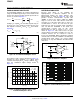
A four-quadrant multiplier can easily be implemented Because both inputs of the VCA822 are
using the VCA822. By placing a resistor between FB high-impedance, a difference amplifier can be
and V
IN
, the transfer function depends upon both V
IN
implemented without any major problem. This
and V
G
, as shown in Equation 1 . implementation is shown in Figure 80 . This circuit
provides excellent common-mode rejection ratio
(CMRR) as long as the input is within the CMRR
range of – 2.1V to +1.6V. Note that this circuit does
not make use of the gain control pin, V
G
. Also, it is
recommended to choose R
S
such that the pole
Setting R
1
to equal R
G
, the term that depends only on
formed by R
S
and the parasitic input capacitance
V
IN
drops out of the equation, leaving only the term
does not limit the bandwidth of the circuit. The
that depends on both V
G
and V
IN
. V
OUT
then follows
common-mode rejection ratio for this circuit
Equation 2 .
implemented in a gain of +10V/V for V
G
= +1V is
shown in Figure 81 . Note that because the gain
control voltage is fixed and is normally set to +1V, the
feedback element can be reduced in order to
increase the bandwidth. When reducing the feedback
element make sure that the VCA822 is not limited by
common-mode input voltage, the current flowing
through R
G
, or any other limitation described in this
data sheet.
Figure 78. Four-Quadrant Multiplier Circuit
The behavior of this circuit is illustrated in Figure 79 .
Figure 80. Difference Amplifier
Keeping the input amplitude of a 1MHz signal
constant and varying the V
G
voltage (100kHz, 2V
PP
)
gives the modulated output voltage shown in
Figure 79 .
Figure 81. Common-Mode Rejection Ratio
Figure 79. Modulated Output Signal of the
4-Quadrant Multiplexer Circuit
20 Submit Documentation Feedback Copyright © 2007 – 2008, Texas Instruments Incorporated
Product Folder Link(s): VCA822