
Datasheet


7
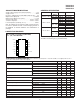
UCC15701/2
UCC25701/2
UCC35701/2
Transitioning From UCC3570 To UCC35701
The UCC35701/2 is an advanced version of the popular,
low power UCC3570 PWM. Significant improvements
were made to the IC’s oscillator and PWM control sec
-
tions to enhance overall system performance. All of the
key attributes and functional blocks of the UCC3570
were maintained in the UCC35701/2. A typical applica
-
tion using UCC3570 and UCC35701/2 is shown in Fig. 6
for comparison.
The advantages of the UCC35701/2 over the UCC3570
are as follows.
Improved oscillator and PWM control section.
A precise maximum volt-second clamp circuit. The
UCC3570 has a dual time base between oscillator and
feedforward circuitry. The integated time base in
UCC35701/2 improves the duty cycle clamp accuracy,
providing better than ± 5% accurate volt- second
clamp over full temperature range.
Separately programmable oscillator timing resistor
(RT) and capacitor (CT) circuits provide a higher
degree of versatility.
An independent SYNC input pin for simple external
synchronization.
A smaller value filter capacitor (0.1mF) can be used
with the enhanced reference voltage.
UCC35701/2 is pin to pin compatible to UCC3570 but is
not a direct drop-in replacement for UCC3570 sockets.
The changes required to the power supply printed circuit
board of for existing UCC3570 designs are minimal. For
conversion, only one extra resistor to set the volt-second
clamp needs to be added to the existing PC board lay
-
outs. In addition, some component values will need to
be changed due to the functionality change in of four of
the IC pins.
The Pinout Changes from UCC3570 are as follows.
Pin 7 was changed from SLOPE to RT (for timing
resistor)
Pin 8 was changed from ISET to VSCLAMP (requiring
one additional resistor from pin 9 to VREF)
Pin 10 was changed from RAMP to CT (single timing
capacitor)
Pin 11 was changed from FREQ to SYNC (input only)
Additional Information
Please refer to the following two Unitrode application
topics on UCC3570 for additional information.
[1] Application Note U-150, Applying the UCC3570 Volt-
age-Mode PWM Controller to Both Off-line and DC/DC
Converter Designs by Robert A. Mammano
[2] Design Note DN-62, Switching Power Supply Topol-
ogy, Voltage Mode vs. Current Mode by Robert
Mammano
APPLICATION INFORMATION (cont.)
VS CLAMP
CT
FEEDBK
SOFT START HIGH DC LO W DC ZE R O DC
SOFTST
V-S CLAMP
SOFT STOP
Figure 1. Timing diagram for PWM action with forward, soft start and volt-second clamp.
TYPICAL WAVEFORMS
UDG-98207