
Datasheet


UCC2897A
SLUS829D -- AUGUST 2008 -- REVISED JULY 2009
8
www.ti.com
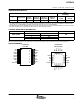
DETAILED PIN DESCRIPTIONS
RDEL
This pin is internally connected to an approximately 2.5-V DC source. A resistor (R
DEL
) to GND sets the turn-on
delay for both gate drive signals of the UCC2987A controller. The delay time is identical for both switching
transitions, between OUT is turning off and AUX is turning on as well as when AUX is turning off and OUT is
turning on. The delay time is defined as:
t
DEL1
= t
DEL2
= 11.1 × 10
−12
× R
DEL
+ 15 × 10
−9
seconds
For proper selection of the delay time refer to the various references describing the design of active clamp power
converters.
RON
This pin is internally connected to an approximately 2.5-V DC source. A resistor (R
ON
) to GND (pin 6) sets the
charge current of the internal timing capacitor. The RON pin, in conjunction with the ROFF pin (pin 3) are used
to set the operating frequency and maximum operating duty cycle.
ROFF
This pin is internally connected to an approximately 2.5-V DC source. A resistor (R
OFF
) to GND (pin 6) sets the
discharge current of the internal timing capacitor. The RON and ROFF pins are used to set the switching period
(T
SW
) and maximum operating duty cycle (D
MAX
) according to the following equations:
t
ON
= 36.1 × 10
−12
× R
ON
×
S
Ω
− t
DEL
(s) seconds
t
OFF
= 15 × 10
−12
× R
OFF
×
S
Ω
+ t
DEL
(s) + 170 × 10
−9
× (s) seconds
T
SW
= t
ON
+ t
OFF
D
MAX
=
t
ON
t
ON
+ t
OFF
(1)
(2)
(3)
(4)
(5)