
Datasheet


UCC2897A
SLUS829D -- AUGUST 2008 -- REVISED JULY 2009
25
www.ti.com
ADDITIONAL APPLICATION INFORMATION
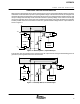
While the same arrangement can be used in a forward type converter, the bootstrap winding off the main power
transformer would not be able to provide a quasi-regulated voltage. In the forward converter, the voltage across
the bootstrap winding equals the input voltage times the turns ratio. Accordingly the bias voltage would vary with
the input voltage and most likely would exceed the maximum operating voltage of the control circuits at high
line. A linear regulator can be used to limit and regulate the bias voltage if the power dissipation is acceptable.
Another possible solution for the forward converter is to generate the bias voltage from the output inductor as
shown in Figure 11.
VIN
GND
VDD
Synchronous
Rectifier
Control
LOAD
UCC2897A
Bootstrap Bias 1
C
BIAS
Q
MAIN
+V
IN
C
IN
-- V
IN
Figure 10. Bootstrap B ias 1 , Flyback Example
This solution uses the regulated output voltage across the output inductor during the freewheeling period to
generate a quasi-regulated bias for the control circuits.
C
BIAS
Q
MAIN
+V
IN
C
IN
-- V
IN
VIN
GND
VDD
Synchronous
Rectifier
Control
LOAD
UCC2897A
Bootstrap Bias 2
Figure 11. Bootstrap Bias 2, Forward Example