
Datasheet


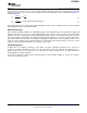


Table Of Contents
- NATURAL INTERLEAVING FEATURES
- SYSTEM FEATURES
- APPLICATIONS
- CONTENTS
- DESCRIPTION
- ABSOLUTE MAXIMUM RATINGS
- DISSIPATION RATINGS
- RECOMMENDED OPERATING CONDITIONS
- ELECTROSTATIC DISCHARGE (ESD) PROTECTION
- ELECTRICAL CHARACTERISTICS
- DEVICE INFORMATION
- TYPICAL CHARACTERISTICS
- APPLICATION INFORMATION
- Theory of Operation
- On-Time Control, Maximum Frequency Limiting, and Restart Timer
- Natural Interleaving
- Phase Management
- Zero Crossing Detection and Valley Switching
- Brownout Protection
- Failsafe OVP—Output Over-Voltage Protection
- Over-Current Protection
- Phase Fail Protection
- Distortion Reduction
- Improved Error Amplifier
- Open-Loop Protection
- Soft-Start
- Light-Load Operation
- Command for the Downstream Converter
- VCC Undervoltage Protection
- VCC
- DESIGN EXAMPLE
- ADDITIONAL REFERENCES

T Temperature C°
J
- -
110
105
100
95
90
80
-40 -20 0 20 40 60 80 100 120
g Transconductance s
- m
m
-
85
5.94V<V <6.06V
SENSE
V OutputVoltage V
COMP
- -
11
10
9
8
7
6
0
0 1 2 3 4 5
I
OutputCurrent
A- m
COMP
-
5
4
3
2
1
V =6.1V
SENSE
T Temperature C°
J
- -
150
145
140
135
130
125
-40 -20 0 20 40 60 80 100 120
I CurrentSenseInputBiasCurrent A- m
CS
-
V InputVoltage V
VSENSE
- -
440
400
360
320
280
240
0
0 0.6 1.2 1.8 2.4 3.0 3.6 4.2 4.8 5.4 6.0
I InputBiasCurrent nA
-
VSENSE
-
200
160
120
80
40
UCC28061
www.ti.com
.............................................................................................................................................................. SLUS837A – JUNE 2008 – REVISED JULY 2009
TYPICAL CHARACTERISTICS (continued)
At VCC = 16 V, AGND = PGND = 0 V, VINAC = 3 V, VSENSE = 6 V, HVSEN = 3 V, PHB = 5 V, R
TSET
= 133 k Ω ; all voltages
are with respect to GND, all outputs unloaded, T
J
= T
A
= +25 ° C, and currents are positive into and negative out of the
specified terminal, unless otherwise noted.
ERROR AMPLIFIER TRANSCONDUCTANCE ERROR AMPLIFIER OUTPUT CURRENT
vs vs
TEMPERATURE OUTPUT VOLTAGE
Figure 5. Figure 6.
ERROR AMPLIFIER INPUT BIAS CURRENT CURRENT SENSE INPUT BIAS CURRENT
vs vs
INPUT VOLTAGE TEMPERATURE
Figure 7. Figure 8.
Copyright © 2008 – 2009, Texas Instruments Incorporated Submit Documentation Feedback 11
Product Folder Link(s): UCC28061