
Datasheet


µA723
PRECISION VOLTAGE REGULATORS
SLVS057D – AUGUST 1972 – REVISED JULY 1999
4
POST OFFICE BOX 655303 • DALLAS, TEXAS 75265
APPLICATION INFORMATION
Table 1. Resistor Values (kΩ) for Standard Output Voltages
OUTPUT
VOLTAGE
APPLICABLE
FIGURES
FIXED OUTPUT
±5%
OUTPUT ADJUSTABLE
±10%
(SEE NOTE 6)
(V) (SEE NOTE 5)
R1
(kΩ)
R2
(kΩ)
R1
(kΩ)
P1
(kΩ )
P2
(kΩ )
3.0 1, 5, 6, 9, 11, 12 (4) 4.12 3.01 1.8 0.5 1.2
3.6 1, 5, 6, 9, 11, 12 (4) 3.57 3.65 1.5 0.5 1.5
5.0 1, 5, 6, 9, 11, 12 (4) 2.15 4.99 0.75 0.5 2.2
6.0 1, 5, 6, 9, 11, 12 (4) 1.15 6.04 0.5 0.5 2.7
9.0 2, 4, (5, 6, 9, 12) 1.87 7.15 0.75 1.0 2.7
12 2, 4, (5, 6, 9, 12) 4.87 7.15 2.0 1.0 3.0
15 2, 4, (5, 6, 9, 12) 7.87 7.15 3.3 1.0 3.0
28 2, 4, (5, 6, 9, 12) 21.0 7.15 5.6 1.0 2.0
45 7 3.57 48.7 2.2 10 39
75 7 3.57 78.7 2.2 10 68
100 7 3.57 105 2.2 10 91
250 7 3.57 255 2.2 10 240
–6
(see Note 7)
3, 10 3.57 2.43 1.2 0.5 0.75
–9 3, 10 3.48 5.36 1.2 0.5 2.0
–12 3, 10 3.57 8.45 1.2 0.5 3.3
–15 3, 10 3.57 11.5 1.2 0.5 4.3
–28 3, 10 3.57 24.3 1.2 0.5 10
–45 8 3.57 41.2 2.2 10 33
–100 8 3.57 95.3 2.2 10 91
–250 8 3.57 249 2.2 10 240
NOTES: 5. The R1/R2 divider can be across either V
O
or V
(ref)
. If the divider is across
V
(ref)
, use the figure numbers without parentheses. If the divider is across
V
O
, use the figure numbers in parentheses.
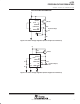
6. To make the voltage adjustable, the R1/R2 divider shown in the figures must
be replaced by the divider shown below.
R1
P1
R2
Adjustable Output Circuit
7. For Figures 3, 8, and 10, the device requires a minimum of 9 V between V
CC+
and V
CC–
when V
O
is equal to or more positive than –9 V.