
Datasheet


TVP5160
SLES135E–FEBRUARY 2005–REVISED APRIL 2011
www.ti.com
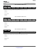
Table 3-54. GPIO Input 2
Subaddress 41h
Read only
7 6 5 4 3 2 1 0
AVID GPIO GLCO VS HS FID C_9 C_8
AVID input pin status:
0 = Input is a low
1 = Input is a high
GPIO (Pin 82) input pin status:
0 = Input is a low
1 = Input is a high
GLCO input pin status:
0 = Input is a low
1 = Input is a high
VS input pin status:
0 = Input is a low
1 = Input is a high
HS input status:
0 = Input is a low
1 = Input is a high
FID input status:
0 = Input is a low
1 = Input is a high
C_x input status:
0 = Input is a low
1 = Input is a high
These status bits are only valid when pins are used as input and its states updated at every line.
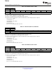
Table 3-55. Back End AGC Status 1
Subaddress 44h
Read only
7 6 5 4 3 2 1 0
Gain [7:0]
Current back end AGC ratio = Gain/128
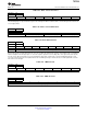
Table 3-56. AFE Coarse Gain for CH 1
Subaddress 46h
Default 20h
7 6 5 4 3 2 1 0
CGAIN 1 [3:0] Reserved
CGAIN 1 [3:0]: Coarse Gain = 0.5 + (CGAIN 1)/10 where 0 ≤ CGAIN 1 ≤ 15
This register only works in manual gain control mode. When AGC is active, writing to any value is ignored.
1111 = 2
1110 = 1.9
1101 = 1.8
...
0010 = 0.7(default)
0001 = 0.6
0000 = 0.5
64 Internal Control Registers Copyright © 2005–2011, Texas Instruments Incorporated
Submit Documentation Feedback
focus.ti.com: TVP5160