
Datasheet


RTC
Mode
45 CLK18 CLK
L
S
B
0
3 CLK
23-Bit Fsc PLL Increment
Start
Bit
1 CLK
RS
M
S
B
22
Reserved
Valid
Sample
Valid
Sample
Valid
Sample
Valid
Sample
128 CLK
128 CLK128 CLK
TVP5160
www.ti.com
SLES135E–FEBRUARY 2005–REVISED APRIL 2011
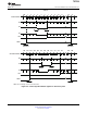
Figure 2-5. RTC Timing
RTC: Reset bit (R) is active low 1 = (R-Y) line normal
Sequence bit (S) PAL:
0 = (R-Y) line inverted
NTSC: 1 = no change
2.5 Output Formatter
The output formatter sets how the data is formatted for output on the TVP5160 output buses. Table 2-2
shows the available output modes.
Table 2-2. Output Format
TERMINAL TERMINAL ITU-R BT.656 20-BIT 4:2:2
NAME NUMBER 10-Bit 4:2:2 YCbCr YCbCr
Y_9 87 Cb9, Y9, Cr9 Y9
Y_8 88 Cb8, Y8, Cr8 Y8
Y_7 89 Cb7, Y7, Cr7 Y7
Y_6 90 Cb6, Y6, Cr6 Y6
Y_5 91 Cb5, Y5, Cr5 Y5
Y_4 94 Cb4, Y4, Cr4 Y4
Y_3 95 Cb3, Y3, Cr3 Y3
Y_2 96 Cb2, Y2, Cr2 Y2
Y_1 97 Cb1, Y1, Cr1 Y1
Y_0 98 Cb0, Y0, Cr0 Y0
C_9 101 Cb9, Cr9
C_8 102 Cb8, Cr8
C_7 103 Cb7, Cr7
C_6 104 Cb6, Cr6
C_5 107 Cb5, Cr5
C_4 108 Cb4, Cr4
C_3 109 Cb3, Cr3
C_2 110 Cb2, Cr2
C_1 113 Cb1, Cr1
C_0 114 Cb0, Cr0
Copyright © 2005–2011, Texas Instruments Incorporated Functional Description 23
Submit Documentation Feedback
focus.ti.com: TVP5160