
Datasheet


ATA/ATAPI Interface Port
11−17
SLLS535E − March 2008 TUSB6250
The unit of recovery time is defined as a single cycle of a 60-MHz clock (16.67 ns), which reflects the t
K
parameter (for multiword DMA) or t
RP
parameter (for ultra DMA) value in an actual ATA/ATAPI drive (see the
ATA/ATAPI-5 specification, pages 294 and 300).
The TUSB6250 state machine automatically adds extra clock cycle(s) to the recovery time setup value based
on the DMA mode used:
• Multiword DMA: two extra clock cycles
• Ultra DMA: one extra clock cycle
Therefore, a 0−31 value in the DMASPRC register corresponds to 2−33 clock cycles of multiword DMA
transfer recovery time or 1−32 clock cycles of ultra DMA transfer recovery time.
The TUSB6250 has a fixed two 60-MHz clock cycle (33.34 ns) write data hold time for multiword DMA write
data transfer, which is part of the additional two extra clock cycle recovery time mentioned above.
76543210
RSV RSV RSV DRCVT4 DRCVT3 DRCVT2 DRCVT1 DRCVT0
R/O R/O R/O R/W R/W R/W R/W R/W
BIT
NAME RESET FUNCTION
4−0 DRCVT[4:0] 00000 DMA transfer speed (recovery time) in the unit of 60-MHz clock cycle.
7−5 RSV 000 Reserved
11.5.16 Data Transfer Mode and Timing Reference Chart
The TUSB6250 firmware builds a default lookup table based on the correlation data between the data transfer
modes and their corresponding timing given in Table 11−4 through Table 11−6. It should be noted that the
assertion and recovery times given here do not reflect the actual performance of the TUSB6250 ATA/ATAPI
data transfer engine. The intention of listing these times is to provide a set of timing values that complies with
the ATA/ATAPI-5 specification requirement. End-product vendors can develop their custom firmware with
different timing settings to be adapted to the actual performance of their drive. The timing below is based on
the 60-MHz clock (using 16 ns as a typical clock-cycle period) that the ATA/ATAPI controller state machine
is running.
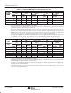
Table 11−4. PIO Mode and Timing Correlation Chart
CYCLE TIME (t
0
) ASSERTION TIME (t
2
) RECOVERY TIME (t
2I
)
PIO
TRANSFER
MODE
TIME
(ns)
TIME
(ns)
# OF CLKS (SEE
NOTE 1)
TIME
(ns)
# OF CLKS (SEE
NOTE 1)
TRANSFER
MODE
SPEC
(MIN)
ACTUAL
SPEC
(MIN)
ACTUAL
REGISTER
SETTING
ACTUAL
SPEC
(MIN)
ACTUAL
REGISTER
SETTING
ACTUAL
0 600 600.12 290 300.06 17 18 N/A 300.06 16 18
1 383 383.41 290 300.06 17 18 N/A 83.35 3 5
2 330 333.4 290 300.06 17 18 N/A 33.34 0 2
3 180 183.37 80 83.35 4 5 70 100.02 4 6
4 120 133.36 70 83.35 4 5 25 50.01 1 3
Other N/A 600.12 N/A 300.06 17 18 N/A 300.06 16 18
NOTES: 1. All the actual timing listed is based on the 60-MHz clock cycle (16.67 ns) used in the TUSB6250.
• The spec value listed is based on the ATA/ATAPI-5 specification.
• The actual assertion time is obtained based on the consideration that both the register and data transfer timings must be met.
• The actual recovery time is obtained with the consideration to meet both the cycle time and the recovery time value specified in the
ATA/ATAPI-5 specification, after meeting the assertion time.
• Because the TUSB6250 hardware always adds one extra clock cycle to the assertion time value and two extra clock cycles to the
recovery time value, the TUSB6250 firmware must use one less than the desired number of clock cycles for any assertion time and
two less for any recovery time programming value. For example, to achieve 300.06-ns assertion and recovery time for PIO mode
0, instead of using 18 clock cycles as the assertion and recovery time value, the TUSB6250 firmware must use only 17 clock cycles
as assertion time and 16 clock cycles as the recovery time programming value.
• According to the ATA/ATAPI-5 specification, the TUSB6250 firmware can issue an IDENTIFY DEVICE command to determine the
supported modes of the mass storage device and then use the corresponding timing in this table during the data transfer.